* D-16 PO8-6 Cylinder Head Casting
Here are a few pictures of one of these "little"
VTEC single cam cylinder heads. I'll point out a few of the important features of the heads
with each picture.
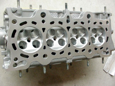
This is a finished customer's cylinder head. The intended
application is normally aspirated with occasional nitrous at the drag races.
It's been completely reworked, flowed, tweaked, cc'd, decked, de-burred, and
finally ready for assembly.
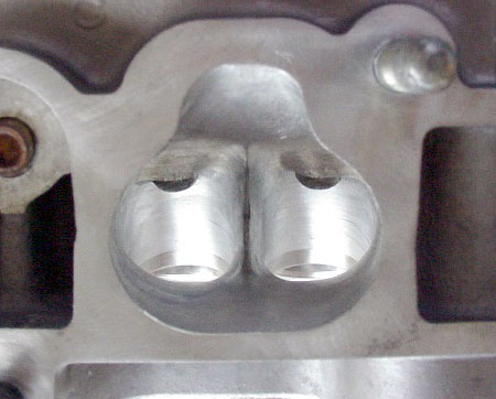
Here's a view of a finished intake port. The entry has been
enlarged by approximately .020" all around, to make sure that the exit in
the manifold runner is smaller, creating a step to fight reversion.
Note that the aluminum valve guide bosses have been faired
into the port roof. The minor rounding of the protruding iron guides is of
little importance, so don't get carried away on them.
The sidewalls have had minimal material removal, while
still making up for the considerable coreshift in this particular casting. Note
that the divider has been purposely kept slightly rounded for this application.
The finish on the entire port is the result of
"scrubbing" with 40 grit at 4,100 rpm. This particular finish promotes
good atomization of the mixture. The finish tapers to 80 grit in the last
.50" prior to the valve seat inserts. As you can see, the seat rings are
purely an extension of the port and the transition from bowl to seat is not noticeable
to the feel.
The port corner radiuses have been decreased to widen the
short turn radius (similar to the B-16 head). The valve guides are maintained at
stock height, but the aluminum bosses have been reduced in size and faired into
the port roof. The divider has been narrowed and the side walls have each been
contoured to equalize their lengths.
Note that the size of the port exit has not been enlarged
greatly, although there has been an attempt made to radius the side wall to exit
transition, so the convergence isn't so abrupt.
If you look closely, you'll be able to see a faint scribe
line around the port exit. This line represents the maximum exit size that can
be successfully "stepped" into the header primary tubes. This is
assuming that the flange entries are of stock Honda gasket size. Note that the
port exit is just a bit smaller than the scribed shape. This will insure that
there will be at least a .070" step at the top and bottom of the port and
.040" on each side. Making sure that there's such a mismatch is essential
for best performance.
We'll look at some chamber side views next.
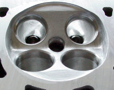
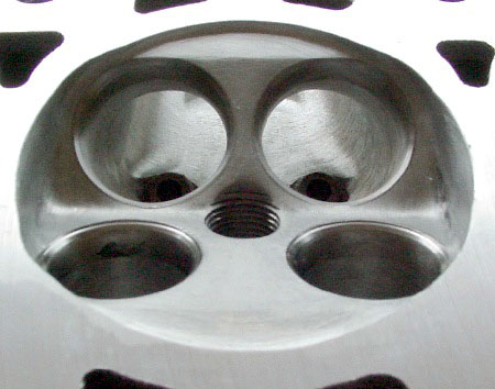
This is a detail shot of the combustion chamber looking out
the exhaust port. Note that the exhaust guides have been faired-in to the roof
and the valve seats are fully radiused into the bowls. This view also shows that
our chamber finishing isn't the mirror-shine that many people love to look at. I
haven't found a piston yet that indicated that it wanted to look at a
"prettier" combustion chamber. This particular finish will aid the
build-up of carbon based crystals, which are essential for making power. The
recessed quench pads on both sides of the chamber have been milled to specific
depths, with the intake side's quench being only 60% that of the exhaust. Our
no-reversion intake valve seat configuration is also evident in this view.
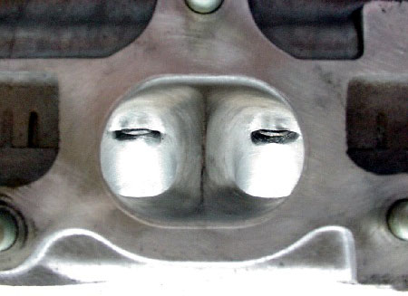
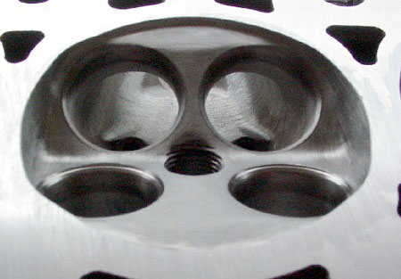
This is a view from the chamber, looking out the intake
ports. While resolution isn't good, the blended guides and transitions from
side-walls to bowls are visible. The single angle anti-reversion intake valve
seats are apparent, as is their blended (extension of port) configuration.
Here's another look with a slightly different angel and contrast:
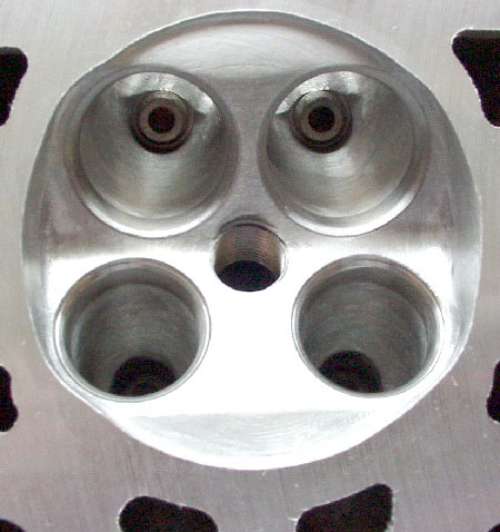
This photo and the one that follows are just to provide
some "other-angle" viewing of the chamber and valve seat layouts. Of
particular interest is the fact that the corners of the chamber have been opened
up to de-shroud the intake and exhaust valves. As the exhaust valves are
"spread" to the outer limits of the chamber to make room for the VTEC
mechanism, it's important to provide some more space adjacent to the cylinder
walls for breathing for high performance.
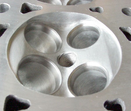
Last Picture.... showing another angle
of the respective seat angles and radiuses.
I hope these pics help some for all the enthusiast-head
porters out there. If nothing else, it should be apparent that there's a reason
for everything visible in these photos. Every area of modification has been
carefully planned and executed for this particular heads mission in the world.
When modifying a cylinder head, it's essential that the
valve seat configurations be designed specifically for the intended application.
All porting must be complementary of the seat configuration. Just as with the
entire engine itself, cylinder heads must be approached as a system, or more
exactly, as where many systems meet. Achieving the proper balance to connect all
these systems should be the goal in the porting exercise.
|