How to build a 2-liter normally aspirated Honda engine
About 1.5 years ago, we assembled a project engine based on a B20 shortblock to test some new piston materials and skirt designs. One thing led to another and almost a year passed before the engine was put to the test during some extensive dyno work.
The combination used a bore diameter of 84.5mm and a lightly reworked and balanced B20 crankshaft, swinging Eagle stock-length rods and our experimental pistons.
We performed all the block mods we do for customers, including posting, boring, honing, decking, reworking the oil galleys and oil filter pad, align honing the mains, aftermarket main cap girdle, one of our modded ITR oil pumps, lightened ITR crank dampener, GSR/ITR windage tray, and last but not least, Moroso pan and pickup.
The top end of the engine utilized a GSR head with our oversize flat-backed intake and exhaust valves, Eibach valve springs, Crower titanium retainers, JUN3 camshafts, and our cam gears. The head was a three-day affair for me and it’s pictured as the “Grocery Getter” in the head modification section of “Components” at: http://www.theoldone.com/
The cylinder head package was also complemented by one of our massively reworked Skunk2 intake manifolds and a Russ Collin’s modified ITR throttle body at 64mm.
On the other end, the header was one of (Hy-Tech) John’s best efforts, with huge stepped primary tubes finally terminating in an under-the-car collector exit
The engine was installed in a racecar, and with no real time for tuning, run at a track, where the results were best described as dismal. The engine would leave hard, and then fall on its face, never making a clean run.
A month of torturous dyno tuning on a Dynojet finally revealed that the fuel pump and pickup in the fuel cell were the culprits. Another month also revealed that the Hondata ECU wasn’t working properly either.
These items were finally fixed and some tuning revealed that this engine had an insatiable appetite for fuel, requiring injectors that were generally reserved for use in boosted applications.
This engine produced torque that nobody’d previously seen from a B series engine of any displacement with power peaking at 280+ at 9500 rpm….and it wasn’t leveling off either.
Just like anyone else, I sometimes become overwhelmed by the moment and the old adage, “if some’s good, more’s better, and too much is best” took hold of my mentality….and that thinking proved costly in the end.
I made the decision to go for more rpm, as this thing would certainly top 300 whp at the rate it was running. I figured that about 10,000 to 10,200 would do it……………and it did. It also blew the engine up.
The quench distance, or piston to head clearance had been set at .032”, to effectively give us “zero” quench clearance at 9500 rpm, due to rod stretch. .032” caused the pistons to hammer the head pretty hard at 10,000+, ultimately work hardening the pistons.
#4 piston was the first to shatter, taking out the cylinder, the cylinder head, and a few more ancillary parts in the process. The debris from #4 was in turn distributed to all the other cylinders, courtesy of the intake plenum chamber, leaving no cylinder exempt from damage.
It was an expensive reminder that one needs to think (hard) before making any hair-brained decisions regarding rpm with any engine. You’d think that I’d have been old enough to know better, but……………...adrenaline can be a terrible thing.
During the past couple years, we’ve built a lot of normally aspirated Honda engines here. Each and every one has caused me to want to feel the “thrill” of one of these NA monsters in one of my own cars. Naturally, building a duplicate of the blown-up engine became the order of the day…when I wasn’t working on customer parts.
Picking a car to install it in was the next decision. My thinking was that the Civic offered the quickest ET potential, but I feared that “CARMA” would prevail and the Civic would kill me if I messed with it’s D series combination that runs so dependably well, leaving me with the two ITR’s I purchased in 1997 as the next options.
One was ruled out, since was my “collectable ITR”, having been put into storage the day it arrived here with 27 miles on the odometer The only choice remaining was my “other” ITR with 5500 on the clock and a blower under the hood.
That decision made, it was time to start the engine project.
In this business time never stands still. We continue to develop better products every day, as do most of the vendors we deal with. Many of you probably think that I’ll be using the absolute latest and greatest, but our customers always have priority for the “good stuff”, and I’m on a budget and the many of the parts we’ll use are machine shop “disasters” and “leftovers” from earlier development programs.
Next decision is on the engine’s displacement. This shouldn’t be an issue, since the previous engine had been built using a 84.5mm bore and a 89mm stroke, but since it’s going in my street car, should I go for more displacement and torque?
Throwing a 95mm stroke Eagle crank into the mix is as simple as grabbing one from stock and fitting it with some .137” (longer-than-stock) Eagle rods and a set of our pistons with the pin raised .250”. It’s terribly tempting, but we’ve yet to see a B series engine make as much power as one of our two liters. Granted, they will handily belt out 180+ ftlbs of torque…..and at reasonably low rpm too, but the LR ratio is close to awful at 1.47-1 and I figure that the combination will wear itself out just as quickly as spinning a two liter two thousand RPM higher for grunt. But damn, that torque is tempting.
The combination that we’re going with is pretty well set now. The block is the poorest of five used CRV blocks that we have left here. Frankly, this one’s a mess. It was originally bored and honed by a local machine shop here in Ft. Worth that “specializes” in import engine machining. Their machine work was an abomination, with the cylinder bores as much as .0016” out of round, with lots of taper to the cylinders from top to bottom. Clearances for the experimental strutted pistons the block was originally sized for range from .0012” to .0029”, which is simply unacceptable by any standards in this day and time. This block also suffered the ill effects of an acid bath (busted battery) in the CRV’s wreck that liberated the engine. I spent about three hours six or seven months ago with all sorts of solutions to neutralize the acid and finally cartridge rolls and a grinder in an attempt to stop the acid’s attack of the block’s exterior.
Now it’s just got a strange look to it, as it’s fairly shiny in places, but it’s heavily pitted everywhere. Even with all the block’s problems, I’m looking to turn this turd into a rose by the time all’s finished
In inspecting the block for structural integrity, the first thing I look for on a B20 is the quality if the aluminum casting that surrounds the 4-in-1 cylinder sleeves. Viewing the block’s deck, there should be no areas where the aluminum wasn’t absolutely flush with the bore casting, especially in the fillets between the adjoining cylinders. All B20 blocks are not created equally in this important area, and if the block isn’t “perfect”, broken cylinders are a certainty.
The cylinder casting that Honda uses in these B20’s is extremely brittle when compared to more resilient “round” individual bore liners. This is simply the nature of a casting such as this where sectional thickness varies so significantly. These cylinders are easily cracked if there’s just a hint of detonation and all it takes to break one of the blocks with the small casting flaws is about 220 HP, so they can certainly be a liability.
The second thing I look for in a block are main bores that are straight and true. I always spin the crank in the blocks when I disassemble a shortblock. If the crank isn’t “free”, the block’s got a problem.
Inspect the main bearings that come from the block as well. Abnormal bearing wear is also a clue that the mains aren’t as straight as we’d like to see.
This particular block has excellent casting integrity around the cylinder casting and the mains are in good shape, so we’ll set it aside for the time being.
I’ve made up my mind that the stroke I’ll use is 89.0mm, so a B18 / B20 crankshaft will be the pick. Once again, I have several cranks here to choose from, but I’ll pick one based on it’s main journal diameters, so overall main bearing thickness will be in the middle of the color chart after the block’s fully machined and ready to assemble.
Since as noted above, these blocks are a bit on the fragile side, I’ll use the old NASCAR trick of “posting” to improve its survival rate. BTW, as a point of interest, there are all sorts of clowns in the import industry claiming to have invented “posting”, but if they weren’t old enough to be building engines in the late 60’s, they’re liars because “posting” had it origins with attempts to strengthen Ford blocks and heads back then. Hell, after looking at some of the hand-built race blocks from the first half of the 20th century, “posting” probably began much earlier than that.
The posting process involves machining and tapping holes in the thrust sides of the block and torquing in threaded aluminum “posts” that physically “connect” the outer part of the cylinder with the outside (peripheral) walls of the block. With these “posts” installed, if the cylinder walls are going to move, they have to move the outside walls of the block too, so they add a tremendous amount of strength, making the block capable of withstanding a lot of abuse. This modification also has no ill effect on cylinder cooling, which is something I’m big on these days.
Since the block is going to run some old 84.5mm development pistons that are unfit for anything except conversation pieces, the next step is to size the cylinders.
The boring and honing process is one that should be accomplished by someone who does little other than cylinder wall preparation. Good boring and honing is an art form / science, and while good equipment is essential, a machinist who has a lifetime of experience (and who charges by the hour rather than having a set price for the operation) is the only way to go, as the right clearances and a good ring seal are all-important to making power. If the rings don’t seal, all the other modifications in the world won’t do you any good, as the power will go right past them.
We bore and hone the block to the same specs we provide our piston customers. All boring and honing operations are referenced from then main bearing bores of the block, so the cylinders will be absolutely perpendicular to the crankshaft. We don’t ever use the engine’s deck surface as a reference point.
The honing process must be performed using Sunnen equipment, such as a CK-10 (or newer) automatic honing machine. BTW, the “automatic” part is a joke, as it still takes a machinist with lots of experience to do it “right”. Right in this case would normally be a clearance of exactly .0028” (to the tenth), with no more than .0001” taper, or out-of-roundness. Our honing expert (who does cylinder wall preparation of winning domestic Pro Stock engines) is also giving the cylinder walls “teeth”, for an even greater effective ring seal. These “teeth” cause the bores to be smooth when you run a finger down the bore, but extremely “rough” when you pull the finger “up” the bore. This texturing is just one of the many “tricks” necessary when competing in a class where all 16 qualifiers are within .02 second on elapsed time! Loose effective ring seal on one of these 500 cubic inch normally aspirated gas-burning engines and you’ll lose a hundred horsepower!
It takes 3 hours of “finesse” time to hone our awful cylinders and before we’re able to get the bores straight and true, we’re looking at .0039” piston to wall clearance….which is “real loose”. We will shrink that clearance to the more desired dimension, however, with some very creative work on the pistons, as you’ll see later on.
This block exhibited some tightness on the #5 main bearings, so while we’re at it, we’re dragging a Sunnen align-hone through the main bores, to insure that all is perfectly straight. With the mains torqued in place (including the block girdle from Z10), there is minimal material removal involved, in fact no material had to be removed from the main caps to affect the cure.
As mentioned above, I’m going to use a crankshaft that has bearing codes that when combined with the block’s codes, will reference bearing thickness that are right in the “middle” of Honda’s bearing chart, so we won’t be using bearings that are too “thick, or thin”. There’s probably no good reason for doing this, but I feel best doing it this way, and when you have as many good Honda (and aftermarket) cranks as we have in inventory, selecting one for bearing fitment is simply the way we do it.
This crank is a B20 unit that has excellent journal finishes from the factory. We will not polish the journals, as this could remove enough material to throw our bearing thickness rational completely out the window…..or worse yet, make the use of Honda bearings impossible.
We’re also going to lighten the crank. On the subject of lightened cranks, let me begin with this….the more power you make, the more mass you have to have in the crankshaft, or harmonics will eat the bottom end up. It’s possible to run cranks that have counterweights you can shave with in lower power engines, such as road racing applications, but this is going to be a near 300Hp combination for my street car, and I’m not planning to be replacing the bearings frequently. We will remove approximately 2 pounds from the crank and then neutral balance it. During the balancing process, we’re also radiusing all the hard edges to reduce drag a bit as the crank is slicing through all the oil raining-down in the crankcase. To reduce rotating mass, I’ll be using one of our Clutch Masters aluminum flywheels to decrease rotating inertia at the largest possible diameter for maximum effectiveness and quick acceleration. The crank pulley I’m using is a new ITR unit that we’ve neutral balanced. This balancer will be replaced shortly with one of the new Fluidamper units that we’re helping them design and test, so the bottom end of this engine should be as vibration-free as we can make it.
Now that the block has been bored, honed, and align-honed, it’s time to make the pistons fit the bores with the .0028” clearance I’m looking for. Since saving the block’s cylinders required additional honing that netted a .0039” clearance, we’re going to build up the diameters of the piston skirts with a unique ceramic coating that also affords extreme lubricity…or lower friction. This process is similar to dry-film lubricants most of you are accustomed to seeing, but the material we’re using is much more wear resistant and can withstand extreme pressures. Its application requires a reasonably complex component preparation process and a lengthy heat curing cycle.
Once applied and cured, we are able to block-sand the skirts (with 800 grit wet cloth) until the correct diameter .120” above the bottom of the skirt tang is obtained to achieve my .0028” clearance objective.
As I stated earlier, the pistons I’m using are some early development strutted pieces and their domes aren’t the latest or greatest, but the pistons are “free” and I’ll make do. The valve reliefs on this set were moved outboard for use with an experimental head, which was milled more than .040”.
After massaging the domes, rounding all the corners and edges, we’re also carefully radiusing the edges of the valve reliefs and the edges of the Roller-Wave reflector slot on the exhaust side of the pistons.
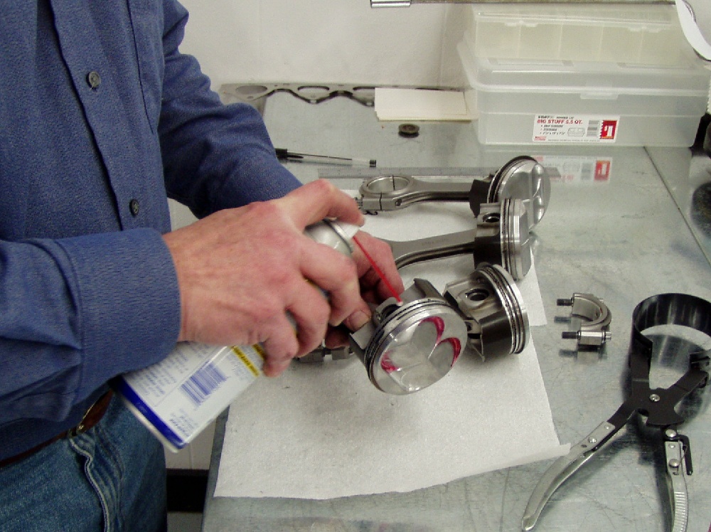
I have individual “dummy” cylinders, which have inside diameters machined to the exact bore sizes of all the pistons we sell. These cylinders are used to duplicate the engines bores when flowing heads on our flow bench and they also serve as tool for CCing pistons. We seal the edges of the piston with red grease and insert it into the cylinder, achieving a leak-tight seal where the ring pack meets the ID of the cylinder. The piston is then pushed down to a depth that will allow the highest part of the dome to be just below the edge of the cylinder. This distance is measured with a depth micrometer for future calculations. A light grease seal is used to seal the Plexiglas plate to the top of the cylinder and fluid from a burette is metered into the area between the piston dome and the Plexiglas plate. If we calculate the volume of the cylinder down to the depth the piston is placed, and then subtract the volume of the fluid we used to fill the space above the piston top, we have the CC displacement of the piston dome. These pistons net 6.59CC’s, which is lower than we’d like, but remember that those relocated valve reliefs I talked about are really costing us valuable positive volume.
Next, we’re going to put the crankshaft in the block, suspended by the two end main caps (using some old bearings). We’ll take one of the rods we plan to use (in this case some standard issue Eagle units which are .137” longer than stock and assemble a piston on it. No piston pin clips are necessary for this “operation”.
The piston/rod combination is placed in #1 cylinder with the crank at exact top dead center. A depth micrometer is then used to measure the distance from the block’s deck surface to the quench pad on the intake side of the piston. This operation is repeated in #4 cylinder and each measurement is recorded.
This engine has -.019” piston to deck clearance, so we’ll mill .017” off the top of the block to yield a final deck clearance of -.002”, meaning that the pistons are .002” “in the hole”.
We deck the blocks parallel to the main bores, making absolutely sure the deck is perfectly perpendicular to the cylinder bores in every axis.
The top of the block is then carefully de-burred to remove sharp edges and any possible “tits” of aluminum that could become unwanted debris in the cylinders or water jacket. Removing all the edges also prevents cut fingers during block handling.
I’m also using a minimal chamfer at the tops of the cylinders to ease the ring’s insertion into the cylinders during assembly, but I stress that it’s “minimal” and a good ring compressor will be necessary to install the piston/ring/rod assemblies without damaging the rings. Excessive chamfers at the top of the cylinder make assembly easy, but since they under-hang the head, they represent crevice-space that unburned hydrocarbons love to hide in, contributing to combustion inefficiency.
Next up for the block is enlargening the oil gallery that connects the oil pump to the oil filter pad on the firewall side of the block. We also polish the entire length of the galley and do considerable grinding inside the oil filter pad as well…all in an effort to reduce pumping losses in the oil system. The individual oil ports inside the maim bearing saddles are also smoothed and thoroughly de-burred.
With every screw-in plug removed, the block is then scrubbed with hot soapy water several times and the cylinder bores are carefully wiped with Bounty paper towels and lots of WD40. After the block has been blown thoroughly dry, it’s bagged and rolled into the assembly room.
The rest of the engine has been in work simultaneously.
The cylinder head is a GSR piece that we got in a trade. Its original owner had “ported” on it and we declined to touch it once it arrived here a couple years ago. We traded him a GSR head, which once ported, made a much more suitable combination for his usage.
This “reject” head was to become a flow bench-only piece, but I figured that, assuming it doesn’t leak water, or oil into the ports, I could possibly make it work well enough for a street head on my 2-liter combination.
The first operation in preparing the head was to mil the deck of the head so that it’s absolutely flat and parallel to the camshaft bores of the head. We have a special fixture for doing this on our Peterson milling machine, so setting it up is quick and easy.
The valve guides in this head were in excellent condition, so the next step is to machine the valve seats and the adjacent chamber radii for the 84.5mm bore we’re using. This is accomplished on a Serdi machine and all intake and exhaust seats are referenced to a tolerance of +/_ .0005” relative to each other and the head’s deck. This is extremely important, as we want all the valve heights to be the same in each chamber, yielding accurate chamber volumes and piston to valve clearances. All the porting and asymmetric seat radiusing will now take place. After a couple day’s effort, all the porting / chamber work is complete and the seats are machined again and dropped .001” referenced from their original pre-ported locations. The head’s now ready for nit picking on the flow bench.
I’ve discussed what we do to the heads on our old BBS enough that I’m not going there in this article, but I am including the flow rates with our highly modified intake manifold and 64mm throttle body attached. The exhaust flow was also measured with 10” long primary tubes attached, which are the exact diameter of their counterparts on the real Hy-Tech header.
The flow numbers are corrected and rated at a pressure drop of 28” H20, which has become an industry standard in the racing community over the last 30 years. Just as a point of interest, much of the intake port and manifold development in NASCAR and Pro Stock these days is done using test pressures of 100” H2O (or more) for greater validity in the real world.
In our development on these pieces we’ve used a low pressure of 14”H20 and a high of 68” H2O for testing. The lower end of the scale is meaningful for low rpm operation, while the higher test pressures show a lot more about what the air and fuel mixture will be doing in the higher rpm ranges.
We’re using .5mm oversize intake and exhaust valves in this head, with the seats machined to relative heights that will cause the intake and exhaust valves to just “miss” each other during overlap with the camshafts we plan to use. These valves have flat combustion chamber sides and are the same pieces we sell customers.
The combustion chambers volumes after rework are 42.4CC, which is small for a head with this sort of chamber rework, but the head had been milled about .010” by it’s previous owner. I want to see a chamber volume of 41.0CC to achieve the compression ratio I’m after, so we’ll mill the head to obtain this chamber volume. Final static compression calculates to 13.44-1 for this combination.
While we’re working with the head, it’s time to check the clearance between the underside of the spring retainers and the top of the valve seals. If we run camshafts with more than .515” lift at the valve, there’s not sufficient space for the seal atop the guide, so we’re the using Serdi and tool we made that machines the top of the guide (and the seal’s step) to a reduced height by .045”. This will insure that the combination is safe with any of the cams we may run, and it still maintains enough guide length for good valve stability, heat transfer, and excellent wear-ability.
The springs I’m using are some of our new pieces that use an exceptionally clean Japanese wire. These springs can live at over 11,000 rpm with camshafts that have lift in the .550” range and brutal acceleration ramps. These springs also require a set-up height of 1.410” to achieve the seat and open pressure we’re after.
We’re using some of Crower’s +.060” retainers on this head to gain the additional set-up height, but we’re still .025” short of what we need. To remedy this situation, we’ve machined .027” from the under-side of the stock Honda spring seats before treating their head-contact sides to the same ceramic coating that we used on the piston skirts for better lubricity.
Once assembled, the spring height is exactly 1.410” on each valve.
The +.060 retainers present an interference problem with the rocker arms, as their raised edges contact the bottom side of the engine’s rockers, potentially leading to a catastrophic valve train failure (and a ruined engine). To eliminate this situation, each rocker arm is carefully ground and polished beneath the VTEC piston bore to achieve a clearance with the retainer of .040”. The rework of this high-stress area is accomplished so that all grinding and polishing marks run with the length of the rocker arm, rather than across it, which could lead to stress-fracturing.
We’re also installing the camshafts I plan to use in the head prior to final assembly to check their clearances in the cam bores and caps. It’s essential that the caps be torqued for this operation. The cams should spin freely with only some light oil between them and their bores. If the cams are hard to rotate, we locate the offending areas with some machinist’s bluing and massage, or align-hone the bores until the cams are absolutely free.
Now, for all of you who think that we’ve assembled and torn all the parts down “excessively”, let me remind you that we’ve never experiences a seized cam, broken cam, broken retainer, valve, or any other related failure in a Honda head we’ve assembled. You either check all the places where problems could occur, or break parts on down the road, take your pick. While most of the parts we’re using can be easily “bolted-on”, they’re a long way from being “plug-and-play”, just remember that the next time your local shop does a two-hour cam swap. If you don’t check all of these things carefully, you’re setting yourself up for a disaster. Haste makes waste…..and so does inexperience.
With the head’s machining out of the way, we’re going to assemble the number one chamber with valves and a set of our flow bench springs for checking piston to valve clearance once the short block’s assembled.
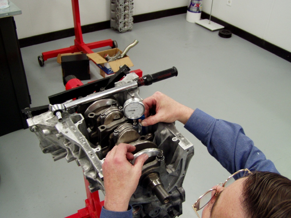
Prior to assembling the short block, we’ve assembled the rods to the crank for a final check of bearing clearances using Plastigage for verification. It’s essential that all the parts (crankshaft, rods, and bearings) be at room temperature (72-75 degrees), or this type measurement can be severely flawed in its results. We’re using a crude wooden fixture to hold the crank while doing this operation, as it’s a hell of a lot easier than doing it with the crank in the block. The Plastigage verifies that the clearances are exactly .0015”, which was what we’d calculated by measuring the crank journals, and bearings. We typically split bearing colors on both the rods and the mains to obtain the clearances we’re after. This is acceptable and preferred practice, unless you “skip” a color, which can lead to problems.
The rods and bearings are numbered for their respective cylinders. Next the pistons’ wrist pins are fitted to the small ends of the rods. All of these rods require some bushing honing to obtain the .0005” that I’m after. After pin fitting is complete the rods are disassembled and thoroughly cleaned along with the pins and bearings.
The crank is bearing fitted to the block in a similar manner with clearances of .0015”. We’re using a modified Z10 girdle, so it’s installed during the bearing fitment process. We’re using new main bolts for final assembly of the bottom end. At the same time we’re checking the fore-and-aft crank travel…..which oddly enough brings up the subject of clutches. Since this will be a high rpm engine and at this point nobody knows whether the clutch used will finally end up being a ClutchMasters low-pressure twin-disk carbon unit, or a CM high-pressure double diaphragm single disk (Kevlar / Ceramic) piece, I’m looking to make the life on the thrust bearings as easy as possible.
Clutches with a lot of pressure plate pressure are tough on thrust bearings (and throw-out bearings). When the clutch is depressed, the crank is being pushed forward into the thrust bearing with the force of the clutch springs. Most CM plates are in the 1900 lb range, which is easy, but a double diaphragm unit can exert as much as 2800 lbs and that’s a load. I’m coating the thrust bearings wear sides with the same ceramics we used on the pistons, and spring seats to help the situation a bit. The dual diaphragm clutch I’m having built has 2,200 lbs of plate pressure, so if it’s the unit I decide to go with, the ceramic coating and a clearance of .005” will insure that the bottom end will be in good shape.
This should give as few of you something to think about on your next clutch purchase…..and when you’re sitting at that traffic light with the clutch pushed in, rather putting the trans in neutral….
The crank is installed in the block using a generous coating of assembly lube on the bearings. We’re only torquing the main caps to 12 ft lbs and we’re not installing the girdle and doing final torquing until the pistons and rods are installed, as it’d just be in the way when we’re guiding the rods home and tightening the rod bolts.
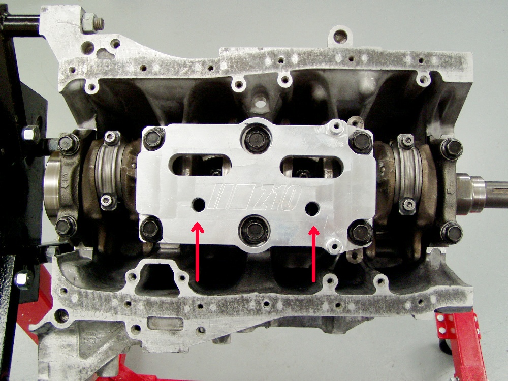
The girdle is a Z10 piece that we’ve doweled to fit precisely with the main caps. I’ve also noted that engines we’ve built in the past with these girdles seem to oil the cylinders more than engines without girdles, so we’ve machined a couple _” holes in the girdle as additional drains for the oil. We’ve also carved some troughs to direct oil to these holes on the crankshaft-side of the girdle. Excessive oil on the cylinder walls can make life difficult for the pistons’ oil rings and that’s something we want to avoid.
The rods are assembled to the pistons, making sure that the bearing “tangs” on the big ends are facing the exhaust side of the pistons, just like Honda does it. Retaining clips are used to keep the pins in place.
I’m using some moly-type assembly lube in the pin bores and in the rods’ bushings for good start-up lubrication and protection. It’s very important that the moly be used sparingly and not on the exterior surfaces of the pistons. If the moly gets on the cylinder walls, it can cause the rings not to seat properly. This is also the reason we never use moly when assembling the valves to the valve guides, as it could be washed into the cylinders during start-up and contaminate the rings/cylinder walls.
The piston rings are gapped at .012” for this engine application and we’re installing them with their gaps “clocked” just as Honda recommends. The pre-fitted rod bearings are inserted in the rods next and lubed with the same moly-type paste we used on the piston pins.
We use WD-40 liberally on the pistons rings and the cylinder walls. This will be the only lubricant we’re using for their assembly. We don’t use motor oil, as we’re trying to create enough initial friction between the rings and cylinders to hasten their seating process. WD-40 also lights-off quite well, which makes engine start-up faster.
I’m using new rod bolts (which weren’t used in the bearing fitting process) for final assembly and we’re lubricating them (and their bolt seats) with the supplied ARP moly paste. I measure and record the length of the rod bolts using a stretch gauge for reference and torque the rod bolts to 28 ftlbs in two steps (1st at 12 ftlbs.). Next we come back and measure the stretched bolt length to confirm that it’s in the optimal +.0051” range.
With the pistons and rods installed in the short block, it’s time to put the modified girdle on and torque the mains. We’re using the factory (GSR) torque settings (and new , well lubed bolts) to button up the lower end.
Rear main seal is standard-issue Honda, and the oil pump is a new ITR unit that we’ve modified to increase efficiency. The windage tray is a new GSR part that’s been trimmed in several places to make it a perfect fit with the Moroso oil pan.
It’s a good idea during earlier “fitting” sessions to fit the oil pan, as well as the pickup, as these things always need some minor massaging before they’ll fit correctly. We also removed about .175” from the flywheel-side of the rear oil pan rail, as experience has shown that a non-modded rail will hit the small bolts protruding through the flywheel. You don’t want to encounter this sort of problem with the engine and transmission installed in the car.
The lower-end is now complete.
As with all the engines we build, this one receives a new water pump. Since it’s going to be a high rpm combination, it’s best to use the ITR/GSR water pump with its larger diameter pulley. This will reduce the pump’s rpm compared to an engine built with the CRV, or LS pump with its smaller pulley diameter. Maintaining good coolant flow is essential on a high output engine, and the CRV/LS pump would spin so fast that cavitation would be a certainty at anything over 7500 rpm.
Since the engine is a hybrid using a non-VTEC block and a VTEC head, supplying oil to the head will be done with an external oil line. We’re taking this opportunity to test the new Golden Eagle oil port adapter that sandwiches between the oil filter and it’s pad, or housing on the backside of the block. It has two outlet ports available. We’re using the larger one to plumb a –6 braided steel oil line to the head, while the smaller port is used for plumbing an oil pressure gauge. Just as a point of interest, we will be running some tests on the dyno soon on another engine to determine the pumping losses (if any) associated with this adapter installed in the system. On this engine, the adapter does an extremely nice job of cleaning up the normal “mess” associated with the external lines.
The crank pulley used is a balanced ITR piece. It has not been lightened, as we’re looking for maximum effectiveness in dampening crank harmonics. When building Honda engines, I always mark the balancers exactly 180 degrees from their original TDC mark. If the balancer is correctly marked, setting the valves becomes an easy task, as all you do it rotate the crank to the proper TDC mark, rather than attempting to “eyeball” cam gear positions.
While we already know that there’s adequate piston to valve clearance, it’s time to do one final fitment session involving the head, on the assembled shortblock. With the valves and lightweight checking springs installed in #1 combustion chamber, we install the head with a .030” head gasket atop the block. The head studs are torqued to no more than 25 ftlbs for this operation. The cams are installed, as are the rocker arms on this cylinder. The rockers we’re using are identically prepared (wiper-pad arc and relief machining) like the rockers we’re going to use in final assembly, except they are all-three linked together, effectively locking them into the Hi-Cam VTEC position. The cam belt is also installed on the engine and we have our own cam gears set to “zero” as a starting point. The valves are lashed to .006” intake and .007” on the exhaust.
A dial gauge is used with the flow-bench adapter plate to measure valve lift (from the top of the spring retainer).
With a degree wheel installed on the front of the crank, we’re able to measure the cams’ lift from .040” (1mm) valve lift valve opening to .040” (1mm) at closure. If we split the number of degrees between the opening event and the closing, we have the cam’s lobe center, which we’ll use to install the cam “straight-up” or at zero. Repeat the procedure with the other side. With the cams properly degreed-in, we can now check the piston to valve clearance and valve-to-valve “clicking” clearance. Pushing down on the rocker arms to make the valves contact the piston, the dial gauge reveals that we have almost .100” exhaust clearance and .080” intake, with a clicking clearance of .030”, which is adequate and “safe” for my engine. During final assembly, I’m using a .036” Cometic head gasket to achieve a piston to head clearance of .038”, so the actual valve clearance will be greater than we measured.
Next, the head’s removed from the engine and assembled with all the valves and other components. We use a special non-moly lubricant when assembling the valves into their guides and genuine Honda valve seals.
ARP studs are used in the block to yield consistent torque values for each head fastener. The deck of the block and the deck of the head are thoroughly wiped free of oil with acetone. Our head gasket is a Cometic B20 style that we had made with a .036” firering thickness. We customarily spread a thin amount of Hondabond around the oil return ports (six of them) on each side of the gasket before installation. This insures that the gasket will properly seal the misaligned oil ports that cause leaks on so many LS/VTEC build-ups. It’s also mandatory that the head-locating dowels be shortened by at least the amount milled from the head and the block, or they can literally hold the head “up” preventing adequate gasket sealing.
The head is torqued to 64 ftlbs, using moly-lube on the studs, as well as their nuts and washers (both sides). The cams are installed next with new Honda oil seals and liberal amounts of moly-lube to make the new rocker arm pads acquaintance with the cams’ lobes a pleasant one.
The timing belt is installed with the cam gears, which we’d previously set. We use a unique locking tool that uses four dowel pins to lock the cam gears (and cams) in place for torquing the bolts that retain the cam gears without over-stressing anything.
We set the valves next, which is an easy task, since we’ve placed a white mark exactly 180 degrees opposite the white TDC mark on the harmonic balancer. Using this method, you set the valve lash for #1 cylinder with the pointer at the TDC mark. To set #3, rotate the crank counter-clock-wise to the new mark. For #4, rotate the crank another 180 to the TDC mark, and for #2, go another half spin to the new mark. With this method, there’s no guesswork to screw things up, and it’s dead-nuts on the money.
The rest of the “bolt-on” components can now be fitted. The header is one of John’s finest and it’s been previously proven to make power in the 300+ range. The exhaust ports in this head have been raised and so have the primary tubes on the header.
I spend all the time that’s needed to trim the header gasket so that it can not protrude into the path of the exhaust flow. This is extremely important and should be done when using any head that has reworked exhaust ports. If there’s any portion of the gasket (or header flange) hanging so it impedes flow, you can kiss all the porter’s efforts good-by.
I’ve discussed the fact many times about exhaust header overlap and I feel that it’s still a necessity, whether your header uses anti-reversion chambers or not. The header primary tube must be larger than the exhaust port exit, period.
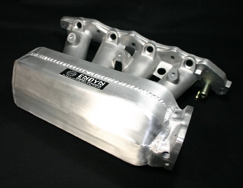
On the intake side, we’re using one of our killer Skunk2 manifolds. We recently flowed the head being used on this project with our single throttle body intake verses a number of different individual throttle body set-ups and the Edelbrock manifold, and we found that our manifold kicked all of their respective asses at every valve lift. We also noted that there was less pressure differential between measuring points with our manifold, translating to better velocity and hopefully a nicer torque curve. Once again, my trusty 64mm throttle body that Russ Collins reworked back in 1997 is being used with this manifold. I’m not going into detail about the manifold’s mods, but there are some pictures of it elsewhere in the article. It weighs 2.3 lbs less than it did when it was stock, if that tells you anything, and we also had to coat the bottom of the plenum and runners with a carbon-filled epoxy to prevent them from sucking shut if the throttle was suddenly closed at high rpm. Sounds scary, right?
We’ve installed some _” vent tubes in the front of the valve cover, which will be plumbed to a second breather tank in front of the engine. These vent tubes must be situated behind the baffle in the top of the valve cover, or you’ll be filling the breather tank up with oil in no time.
There’s another breather tank plumbed from our normal fittings at the rear of the block. It’s simply not possible to have too much breather area on one of these 2-liter N/A engines.
Next step is to remove the engine from it’s stand and mount the clutch / flywheel combination. I’m a bit apprehensive about the operation of this twin disk unit, but we’re going to give it a try. I’m not one to complain too much about delicate clutch engagement, and or difficult transmissions, having learned to drive manual gearboxes in the early 60’s with Jaguar’s old Moss transmissions, which weren’t synchronized! We’ll see how it goes.
Mounting the transmission was easy, however, the casting (brace) that Honda bolts below the clutch housing required major modifications to clear the Moroso oil pan’s corners. 15 minutes with the die grinder “fixed” it. I feel that using the brace to stabilize the transmission (and the block) is extremely important.
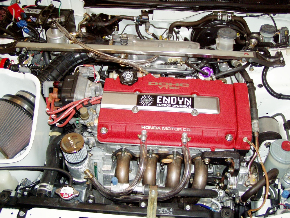
That puts us ready to install in the car. We’ve removed the supercharged ITR engine, so the installation should be a bolt-in…..right.
The installation was relatively uneventful, however, we did modify a number of things including John’s header. The secondary tubes and collector hung a little lower than I wanted, so we cut them and re-welded the pieces to raise the collector up closer to the tunnel…..all-in-all a simple affair. We also did some cutting and welding on the Thermal 3” system under the car to align things better with the header’s collector, eliminating the curved section we used with the blower motor’s Kamikaze header.
The primary O2 sensor is actually mounted just aft the collector flange in the housing that connects to the header’s “donut”. Since this is about 10” further aft than the stock sensor position, I lengthened the wires connected to the sensor. While I was at it, I did the same with the wires connected to the secondary O2 sensor.
The B&M straight stick shifter (with my extension) has always bothered me, so I took the opportunity to heat it and bend the portion above the ball back approximately 1.5” for an easier “reach” from my seated position. While we were at it, we also fabricated a clutch pedal stop to prevent the pressure plate from being over-pressed. Remember this clutch only has about 1.5” of pedal travel. I made some major adjustments on the pedals “cut switch” too, so the engine can be started without pushing the pedal too far downward.
Mounting the breather tanks required a couple brackets that we made in about 5 minutes. I used clear tubing on the feeder lines so we could keep an eye on the system’s oil vapor flow.
Strapped for time, I used a stock (the original) ITR induction tube to connect the throttle body to the air filter. We’ll be making a “Thompson Tube” as soon as we have time….and as soon as Doug is finished with his composite Honda body parts experiments.
We also did a lot of work on the front suspension to get it ready for some serious quarter mile “work” in the future with street legal drag tires. Bushings were removed and replaced, shock valving was changed, and the ride height of the car’s nose was increased .5”.
The engine started instantly. I set the engine’s idle timing at 18 degrees and it’s running with the same “hot-rodded” factory ECU we used with the blower combination for the time being. As soon as the engine’s racked up some break-in miles, we’ll switch over to the MOTEC system, similar to the one we use for dyno room engines. Right now, the engine runs great. It cranks a lot slower than the blower engine…might have to do with a few more points of compression.
Drivability is excellent. It makes a lot of torque, once again due to the compression.
It’s got one of the quickest response times I’ve ever seen on a NA street combination. Just breathe on the “loud pedal” and the revs jump instantaneously. Compression and a light flywheel / clutch can be a wonderful thing.
The clutch operation is going to take some time to grow accustomed to with its short pedal travel. It’s pedal pressure feels lighter than the CM Stage 3, or the stocker for that matter, but it really bites hard. All in all, I think it’ll be the hot ticket.
I’ll update the article with driving impressions, dyno numbers, and performance data as the miles permit.
|
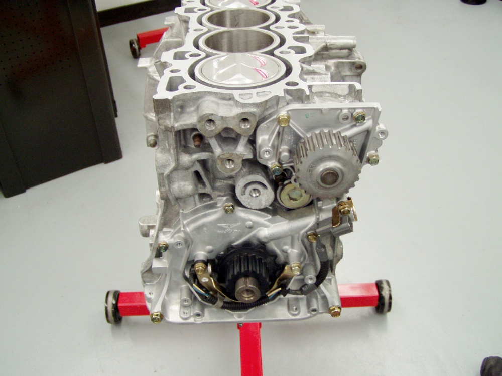
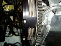
 Here's that old B20 block, exhibiting it's acid-eaten finish. Note the posts
on the intake side (major thrust axis) of the block. These will support the
cylinders under the high loads this engine will be seeing. When we prepare
blocks, all the water, oil gallery, and crankcase access plugs are removed. Here's that old B20 block, exhibiting it's acid-eaten finish. Note the posts
on the intake side (major thrust axis) of the block. These will support the
cylinders under the high loads this engine will be seeing. When we prepare
blocks, all the water, oil gallery, and crankcase access plugs are removed.
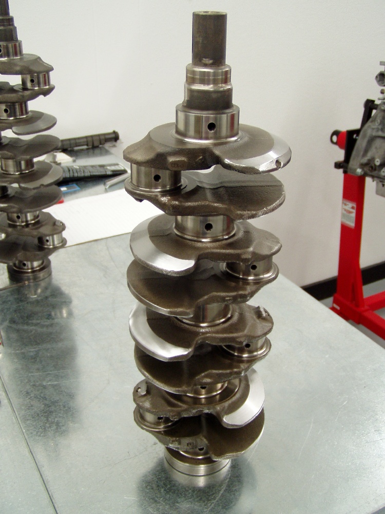
 I picked this particular crankshaft for the engine because it's bearing codes
worked best with those of the block and the rods. The bearings we'll use are in
the "middle" of Honda's thickness chart, rather than "all over
the place" in colors. This is a personal preference of mine and we do the
same thing with every engine we build. I picked this particular crankshaft for the engine because it's bearing codes
worked best with those of the block and the rods. The bearings we'll use are in
the "middle" of Honda's thickness chart, rather than "all over
the place" in colors. This is a personal preference of mine and we do the
same thing with every engine we build.
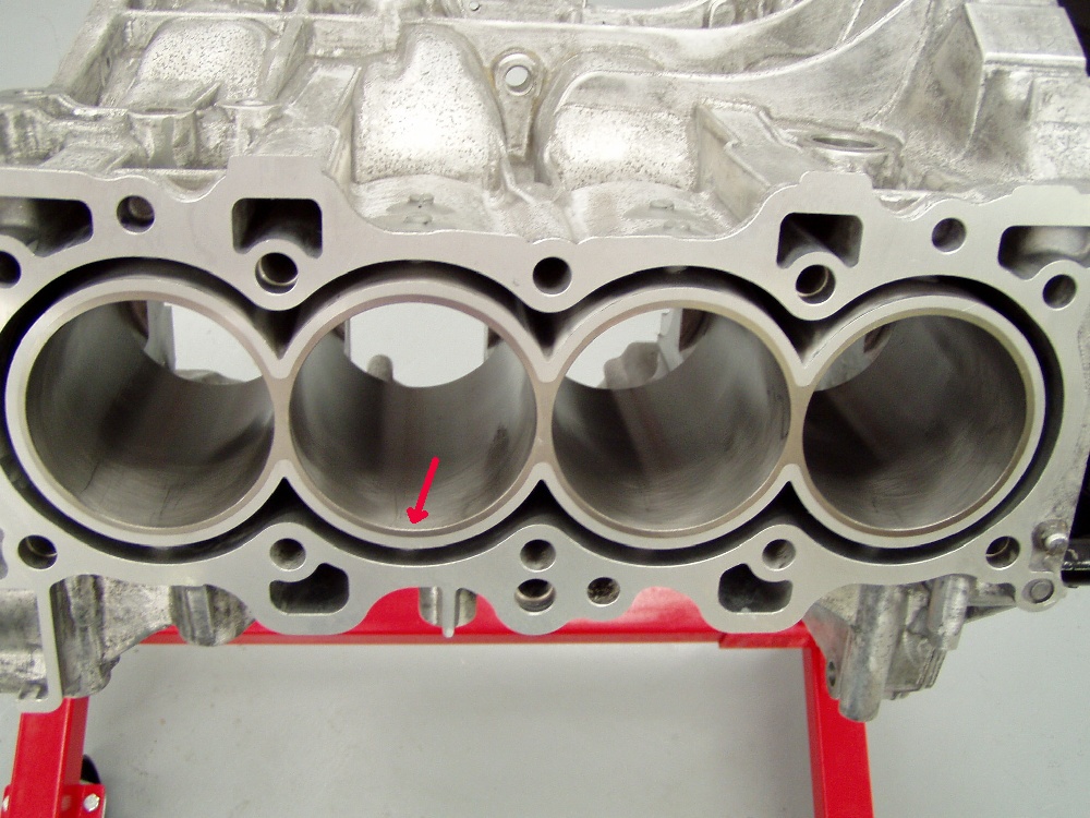
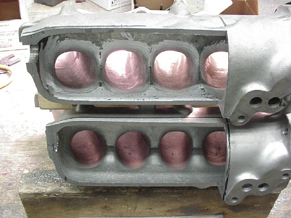
 You can see the small chamfer we use at the tops of the cylinders to
"encourage" the rings to go into the cylinders. If the chamfer is
excessive, the recess it creates under the head will trap large numbers of
hydro-carbons and degrade the combustion efficiency. The small "lines"
you see are tiny shiny spots left by the dial-bore gauge when measuring the
cylinder ID's. You can see the small chamfer we use at the tops of the cylinders to
"encourage" the rings to go into the cylinders. If the chamfer is
excessive, the recess it creates under the head will trap large numbers of
hydro-carbons and degrade the combustion efficiency. The small "lines"
you see are tiny shiny spots left by the dial-bore gauge when measuring the
cylinder ID's.
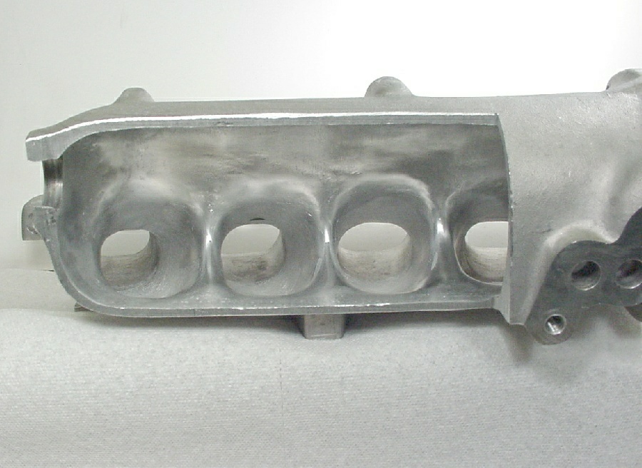
 This close-up of the a cylinder shows the correct hone finish. This finish is
very smooth to the feel as you run a finger down the bore, but it's coarse when
you pull your finger back up. You can see just how small the chamfer is in this
picture. Also visible is the upper cylinder "post" in the water jacket
at the lower right side. This close-up of the a cylinder shows the correct hone finish. This finish is
very smooth to the feel as you run a finger down the bore, but it's coarse when
you pull your finger back up. You can see just how small the chamfer is in this
picture. Also visible is the upper cylinder "post" in the water jacket
at the lower right side.
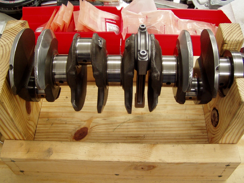
 Here's a picture of our crude fixture for holding the crankshaft during final
bearing fitment for the rods. It's wood, so it can't mar the cranks finish and
we clamp it to the table top so torquing the bolts doesn't rotate the fixture
(or the rods) during the Plastigage operation. It sure beats the hell out of
doing this in the block. The rods and bearings are marked for their respective
journals after we've achieved the desired bearing clearances. Here's a picture of our crude fixture for holding the crankshaft during final
bearing fitment for the rods. It's wood, so it can't mar the cranks finish and
we clamp it to the table top so torquing the bolts doesn't rotate the fixture
(or the rods) during the Plastigage operation. It sure beats the hell out of
doing this in the block. The rods and bearings are marked for their respective
journals after we've achieved the desired bearing clearances.
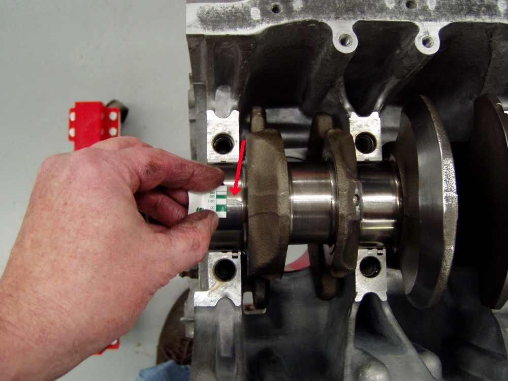
 This picture shows the Plastigage strip on #1 and #2 main journals. Our
calculations on bearing thickness were right on the money, and as you can see,
the plasti-gauge clearly shows that we have .0015" clearance. This picture shows the Plastigage strip on #1 and #2 main journals. Our
calculations on bearing thickness were right on the money, and as you can see,
the plasti-gauge clearly shows that we have .0015" clearance.
 After fitting the main bearings, remove the plasti-gauge, put some light oil
on the bearings, install the crank with the bolts torqued, and spin the crank to
check it for "feel". If the crank spins effortlessly, all's good to
go. This is also when we check the crank's end play. I try to maintain the
low-side of Honda's specs. This engine's clearance was .005". After fitting the main bearings, remove the plasti-gauge, put some light oil
on the bearings, install the crank with the bolts torqued, and spin the crank to
check it for "feel". If the crank spins effortlessly, all's good to
go. This is also when we check the crank's end play. I try to maintain the
low-side of Honda's specs. This engine's clearance was .005".
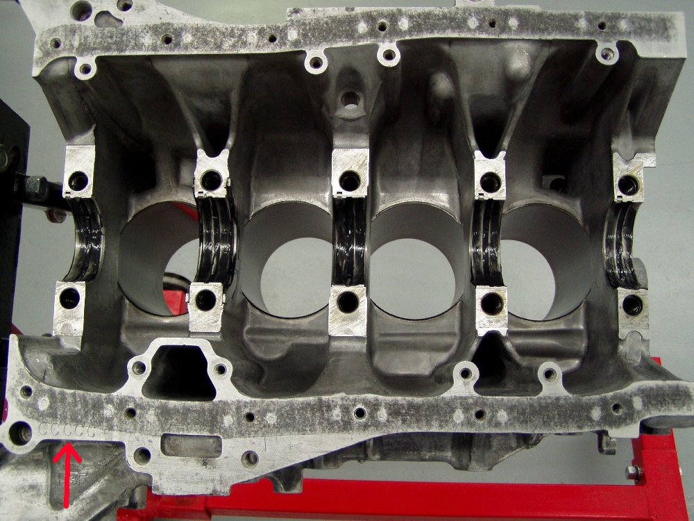
 It's important to use put a good film of lubricant on the main bearings prior
to installing the crank. Note that I've stamped the main bearing code into the
pan rail so it's easy to read. Many blocks from Honda have codes that are damned
near impossible to discern, so I "fix" them at every opportunity. It's important to use put a good film of lubricant on the main bearings prior
to installing the crank. Note that I've stamped the main bearing code into the
pan rail so it's easy to read. Many blocks from Honda have codes that are damned
near impossible to discern, so I "fix" them at every opportunity.
 With the crank in the block, it's also important to lube the bearings in the
main caps. A moderate film of lube is all it takes. With the crank in the block, it's also important to lube the bearings in the
main caps. A moderate film of lube is all it takes.
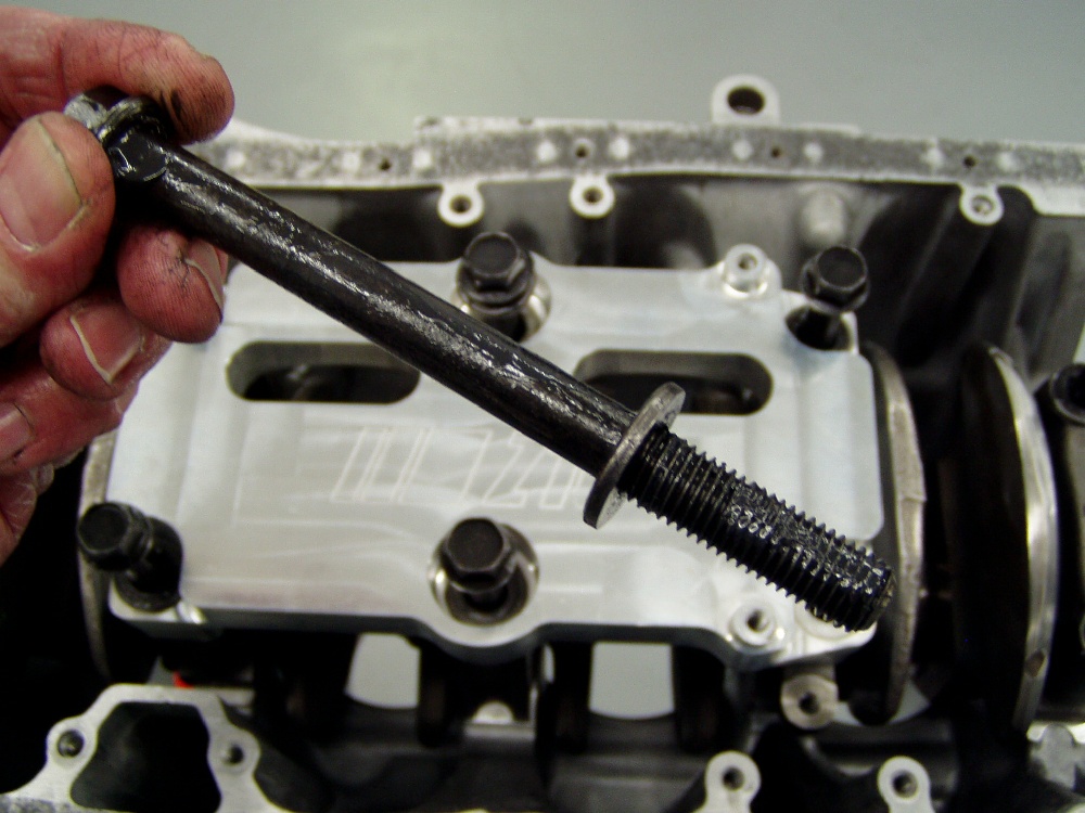
 Don't forget to lube the main bolt threads, as well as the areas above and
below the washer so torque readings will be accurate. If you're wondering why my
hands look dirty, this moly-lube is the culprit. Don't forget to lube the main bolt threads, as well as the areas above and
below the washer so torque readings will be accurate. If you're wondering why my
hands look dirty, this moly-lube is the culprit.
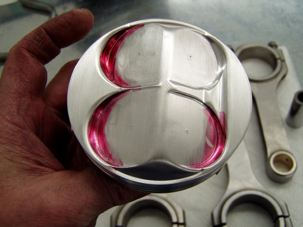
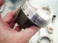
 Here's a view of the dome on the pistons I'm using. This was a set of
"development" pistons from early-on in of the strutted skirt program.
Note the stake marks, which show the centerline of the valves. You can also see
that the scribed valve circumference is well inboard of the edges of the valve
reliefs, causing me to lose about a full CC of dome displacement. The boss
always gets the throw-away pieces! Here's a view of the dome on the pistons I'm using. This was a set of
"development" pistons from early-on in of the strutted skirt program.
Note the stake marks, which show the centerline of the valves. You can also see
that the scribed valve circumference is well inboard of the edges of the valve
reliefs, causing me to lose about a full CC of dome displacement. The boss
always gets the throw-away pieces!
 Here's a view of the skirts on the pistons. As discussed in the article, the
piston to wall clearance was too large, so we coated the skirts with a
high-pressure ceramic coating and block-sanded it to achieve the correct contact
patch and clearance we desired. This coating also has a high coefficient of
lubricity, so not only did it "save" our block and pistons, but it
should help out by reducing friction a bit. Here's a view of the skirts on the pistons. As discussed in the article, the
piston to wall clearance was too large, so we coated the skirts with a
high-pressure ceramic coating and block-sanded it to achieve the correct contact
patch and clearance we desired. This coating also has a high coefficient of
lubricity, so not only did it "save" our block and pistons, but it
should help out by reducing friction a bit.
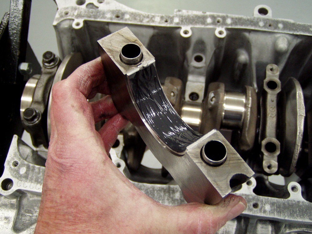
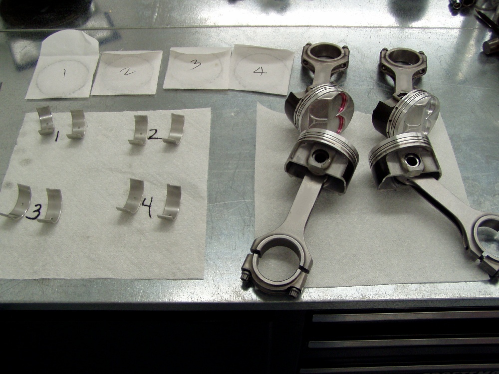
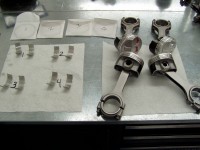 As you can see, we've assembled the rods to the pistons. The bearings that
were fitted and labeled will be inserted next. As you can see, we've assembled the rods to the pistons. The bearings that
were fitted and labeled will be inserted next.
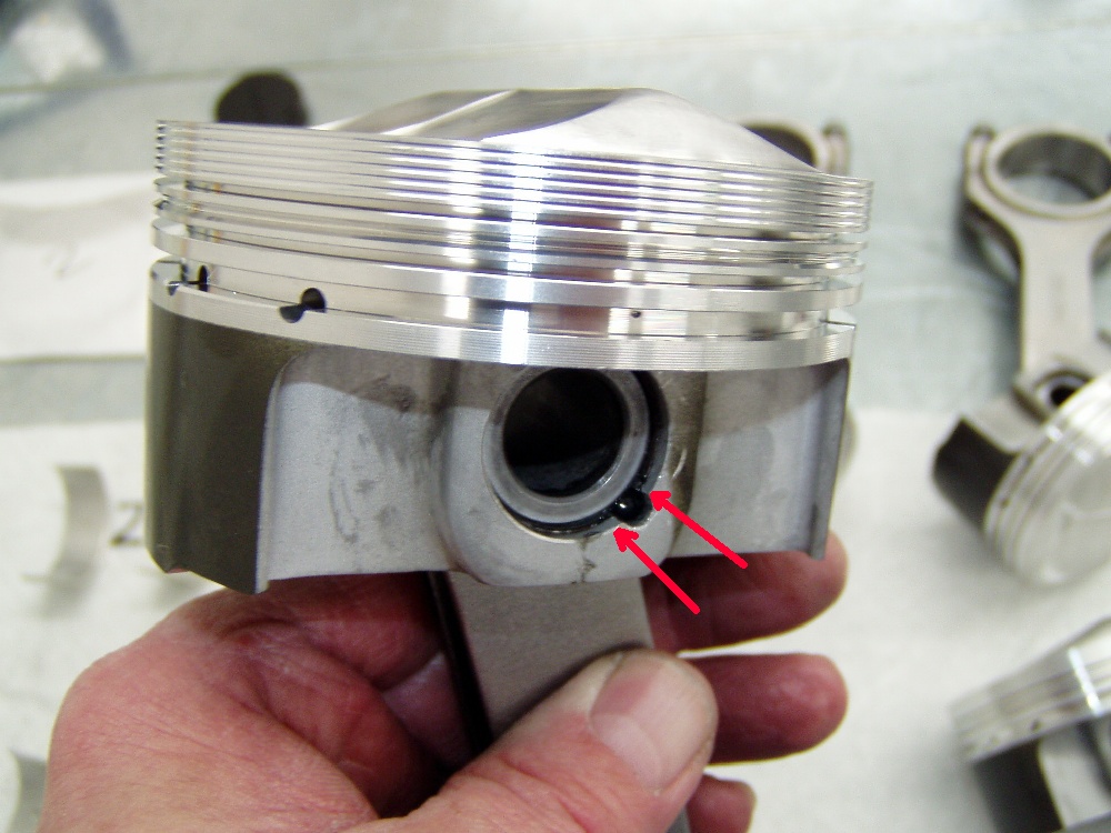
 When assembling the pistons to the rods, I always make sure the ends of the
pin-retaining clips are on either side of the notch in the pin bore. This
insures that they have maximum surface area to "bite". Note that I've
also wiped all traces of moly-lube from the sides of the pin bores in an attempt
to insure than none will reach the cylinder walls, possibly impeding early ring
seating. When assembling the pistons to the rods, I always make sure the ends of the
pin-retaining clips are on either side of the notch in the pin bore. This
insures that they have maximum surface area to "bite". Note that I've
also wiped all traces of moly-lube from the sides of the pin bores in an attempt
to insure than none will reach the cylinder walls, possibly impeding early ring
seating.
 I use WD40 on the piston skirts and rings prior to installing them in the
block. This provides an adequate degree of early lubrication, while still
permitting enough friction for a fast ring break-in. Not the scissors-style ring
compressor that we use. It's not terribly expensive and it sure beats the hell
out of the band-style compressors. I use WD40 on the piston skirts and rings prior to installing them in the
block. This provides an adequate degree of early lubrication, while still
permitting enough friction for a fast ring break-in. Not the scissors-style ring
compressor that we use. It's not terribly expensive and it sure beats the hell
out of the band-style compressors.
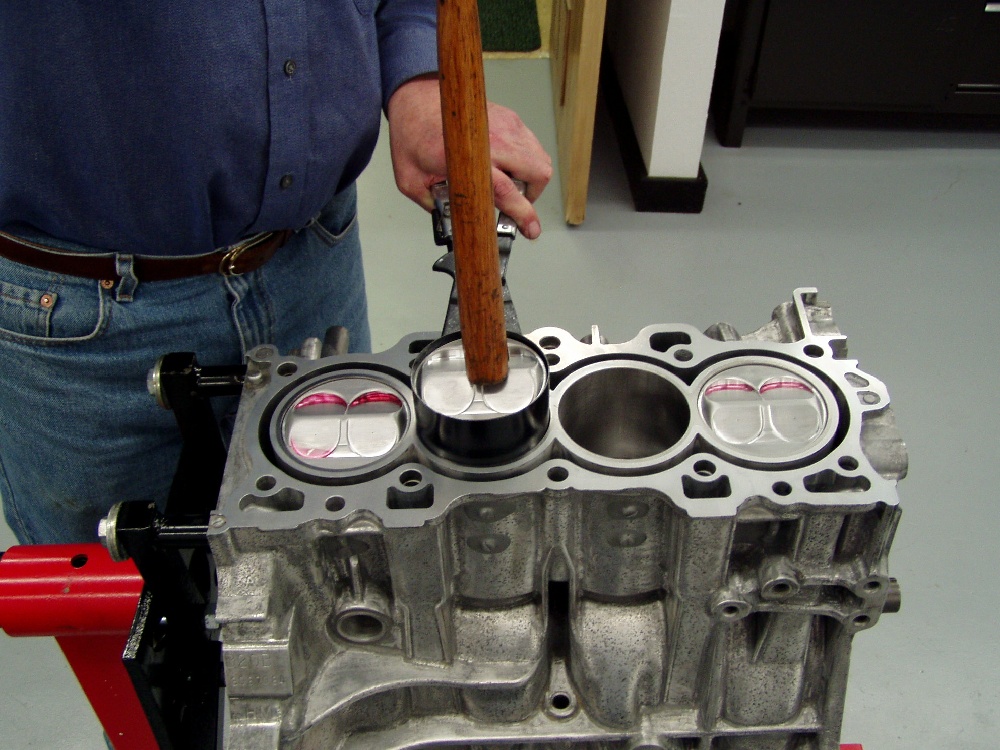
 Installing pistons is simple when everything is prepared correctly. With a
good ring compressor that's correctly squared with the block's deck, all it
takes is a nudge from the hammer's handle. I always put the crank's rod journals
"down" when installing pistons. Installing pistons is simple when everything is prepared correctly. With a
good ring compressor that's correctly squared with the block's deck, all it
takes is a nudge from the hammer's handle. I always put the crank's rod journals
"down" when installing pistons.
 I measure the free length of the rod bolts prior to torquing and afterward, I
measure the stretch to insure that all's within the bolt's specs. Note that I
don't have the center main caps (or the girdle) installed while installing the
piston/rod assemblies, as it makes for a lot more working room. I measure the free length of the rod bolts prior to torquing and afterward, I
measure the stretch to insure that all's within the bolt's specs. Note that I
don't have the center main caps (or the girdle) installed while installing the
piston/rod assemblies, as it makes for a lot more working room.
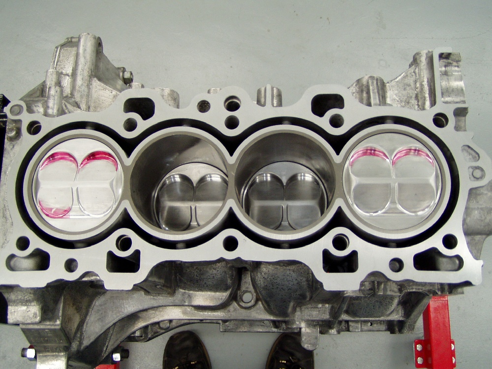
 All four pistons in their new homes. The posts on either side of the
cylinders are visible in this shot. All four pistons in their new homes. The posts on either side of the
cylinders are visible in this shot.
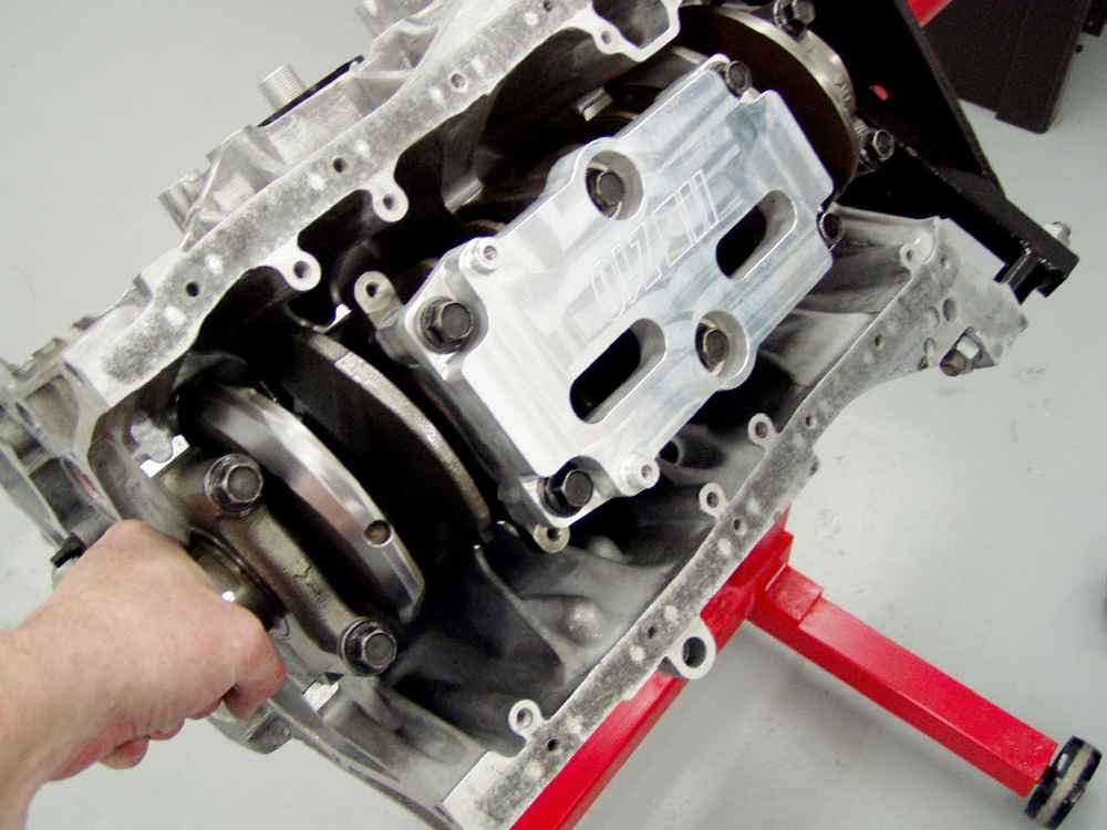
 Be
Before installing the girdle assembly, we machine a couple .625" holes
in it, accompanied by a lot of "sculpting" on the crankshaft side to
help route oil into the sump more efficiently. We torque the main caps to the
factory specs for a GSR/I using new bolts. Be
Before installing the girdle assembly, we machine a couple .625" holes
in it, accompanied by a lot of "sculpting" on the crankshaft side to
help route oil into the sump more efficiently. We torque the main caps to the
factory specs for a GSR/I using new bolts.
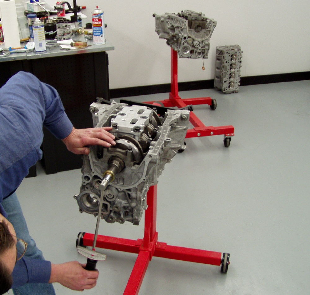
 It's important to check the amount of break-away torque, as well as the
constant torque required to rotate the lower end assembly. Break-away should be
checked with the pistons at mid-stroke and shouldn't exceed 10 ft lbs.
Rotational torque shouldn't exceed 6 ft lbs. It's important to check the amount of break-away torque, as well as the
constant torque required to rotate the lower end assembly. Break-away should be
checked with the pistons at mid-stroke and shouldn't exceed 10 ft lbs.
Rotational torque shouldn't exceed 6 ft lbs.
 The best way to measure deck clearance is with a depth micrometer. We decked
this block to achieve a clearance of - .002", meaning that the flats of the
quench pads are .002" below the block's deck surface. The best way to measure deck clearance is with a depth micrometer. We decked
this block to achieve a clearance of - .002", meaning that the flats of the
quench pads are .002" below the block's deck surface.
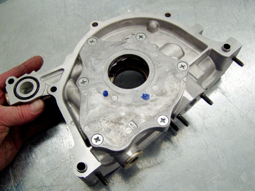
 Next we install one of our modified ITR oil pumps to insure that the engine
will have an adequate and dependable supply of oil. Next we install one of our modified ITR oil pumps to insure that the engine
will have an adequate and dependable supply of oil.
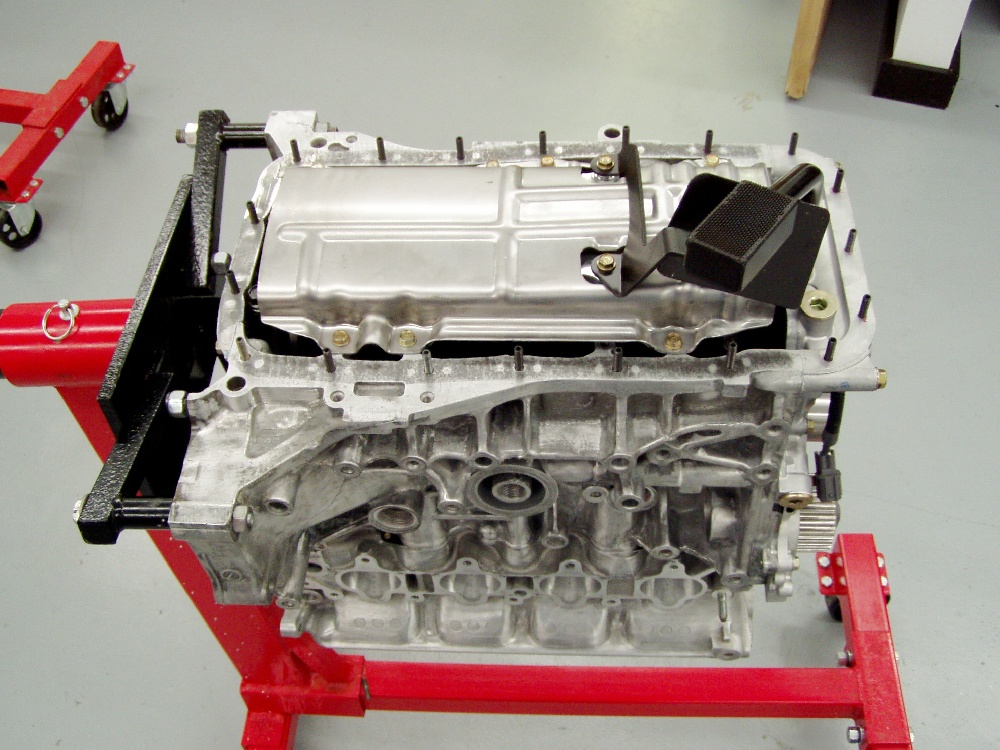
 The bottom end is close to finished with the installation of a
"trimmed" (for proper oil pan fitment) ITR windage tray and the Moroso
oil pick-up. Note that the pan uses studs for mounting rather than the
conventional stud/bolt arrangement. The bottom end is close to finished with the installation of a
"trimmed" (for proper oil pan fitment) ITR windage tray and the Moroso
oil pick-up. Note that the pan uses studs for mounting rather than the
conventional stud/bolt arrangement.
 We're using a new ITR water pump that's had it's vanes trimmed a bit to slow
water flow at extreme rpm levels. Note that we're also using a magnetic sensor
for spark timing. We're using a new ITR water pump that's had it's vanes trimmed a bit to slow
water flow at extreme rpm levels. Note that we're also using a magnetic sensor
for spark timing.
 Prior to finishing the head, we always install the camshafts that the engine
will use. If the cams spin freely and the clearances check out to be within
spec, everything's good. If there's any problem, it's essential that the proper
clearances be achieved, or broken camshafts will result. This is something that
absolutely MUST be checked. If you fail to, don't let me hear you crying when a
camshaft snaps. Prior to finishing the head, we always install the camshafts that the engine
will use. If the cams spin freely and the clearances check out to be within
spec, everything's good. If there's any problem, it's essential that the proper
clearances be achieved, or broken camshafts will result. This is something that
absolutely MUST be checked. If you fail to, don't let me hear you crying when a
camshaft snaps.
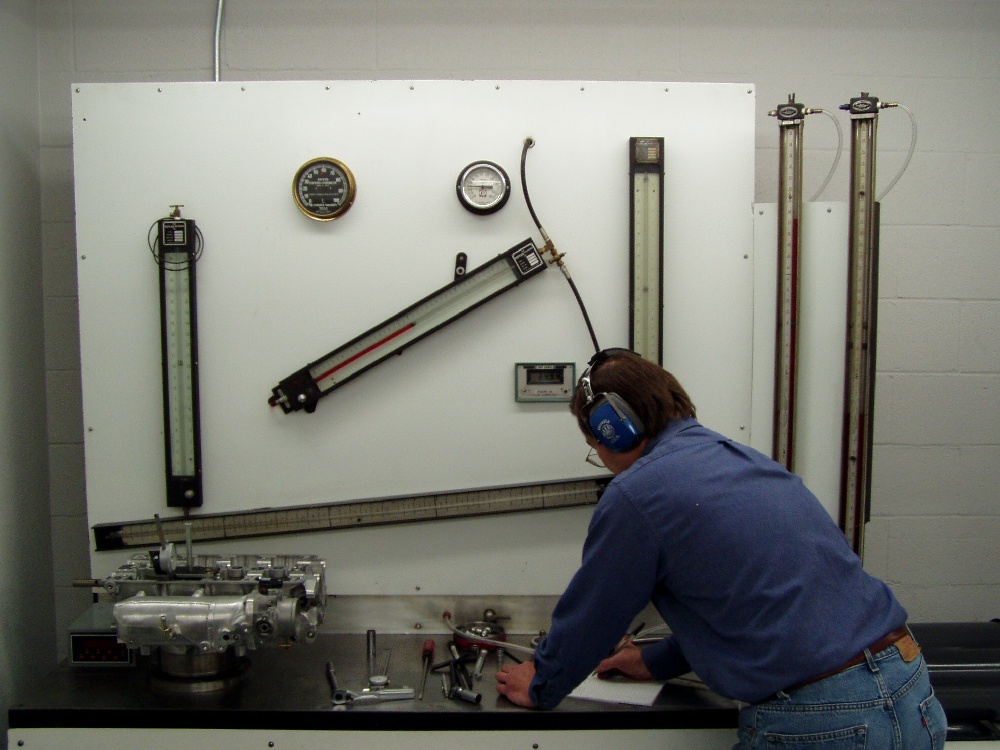
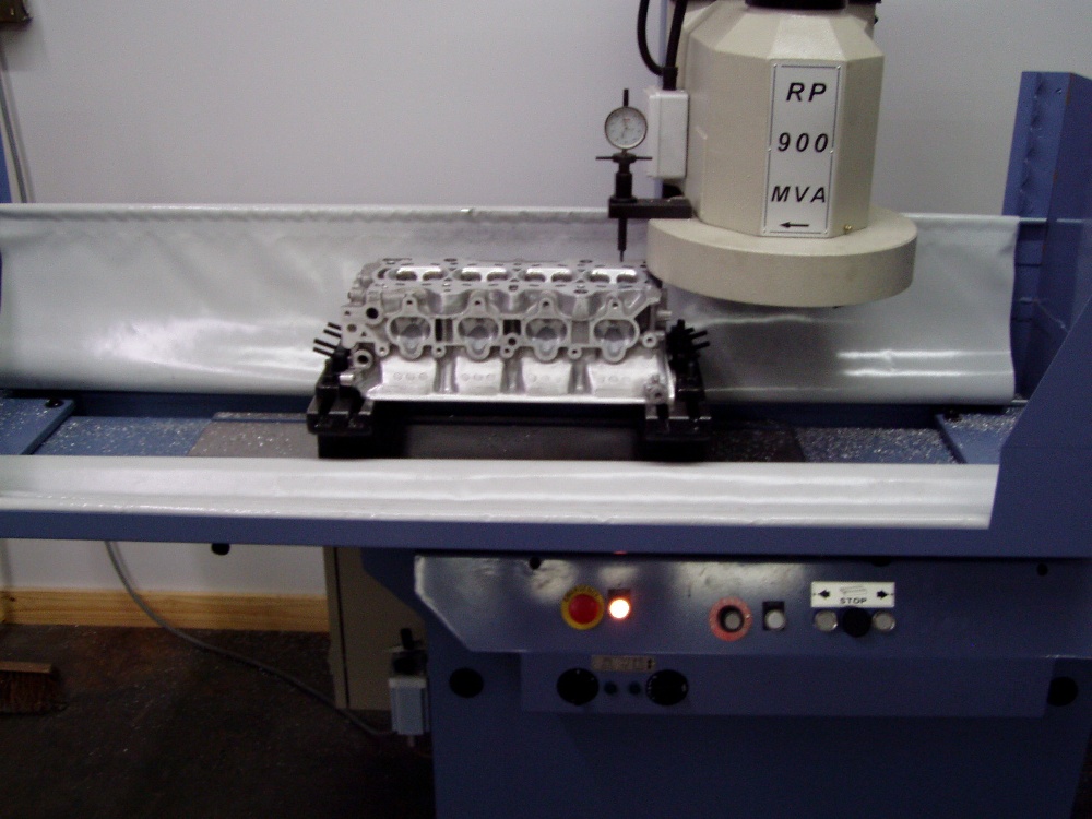
 After all the porting, the head and manifold are analyzed and tweaked on the
flow bench. It's mandatory that the flow rates from cylinder to cylinder are
essentially the same (less than .5% deviation) at all valve lift points. The
manifold is an extension of the intake ports, so it must be in place when
flowing this side of the head. Exhaust pipes and header flange must be similarly
used on the other side to obtain valid data. After all the porting, the head and manifold are analyzed and tweaked on the
flow bench. It's mandatory that the flow rates from cylinder to cylinder are
essentially the same (less than .5% deviation) at all valve lift points. The
manifold is an extension of the intake ports, so it must be in place when
flowing this side of the head. Exhaust pipes and header flange must be similarly
used on the other side to obtain valid data.
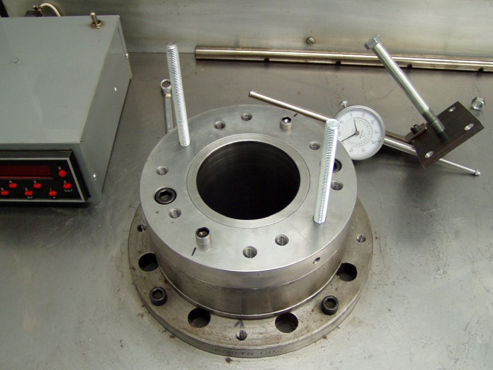
 For valid flow test results, the head must be situated atop a dummy cylinder
of the exact diameter that will be used on the actual engine application. The
length of the cylinder must be at least 1.5 times the engine's stroke. For valid flow test results, the head must be situated atop a dummy cylinder
of the exact diameter that will be used on the actual engine application. The
length of the cylinder must be at least 1.5 times the engine's stroke.
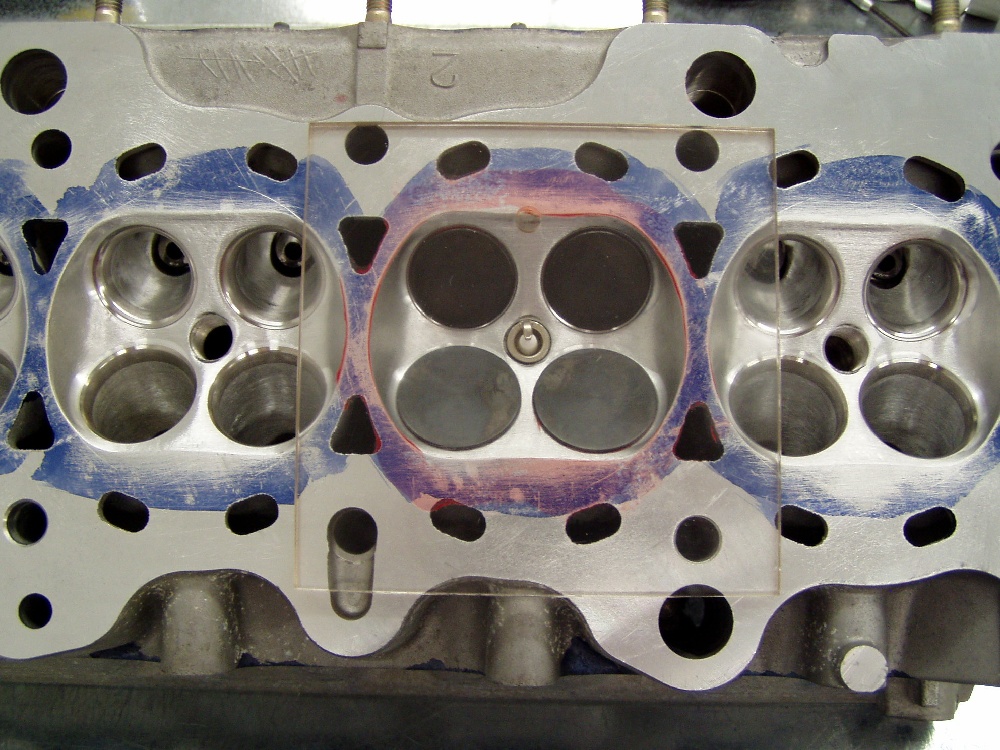
 Once all the port tweaking is complete, it's time to CC the combustion
chambers. We use a spark plug like will be run in the engine, as well as the
valves fitted for each cylinder. Once all the port tweaking is complete, it's time to CC the combustion
chambers. We use a spark plug like will be run in the engine, as well as the
valves fitted for each cylinder.
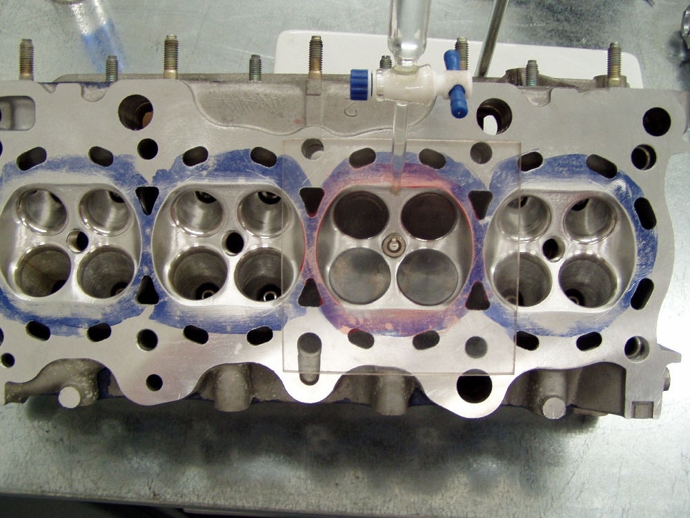
 We use water with just a touch of soap to reduce the surface tension for this
CCing operation. The water must be room temperature for accurate volume
measurements. We use water with just a touch of soap to reduce the surface tension for this
CCing operation. The water must be room temperature for accurate volume
measurements.
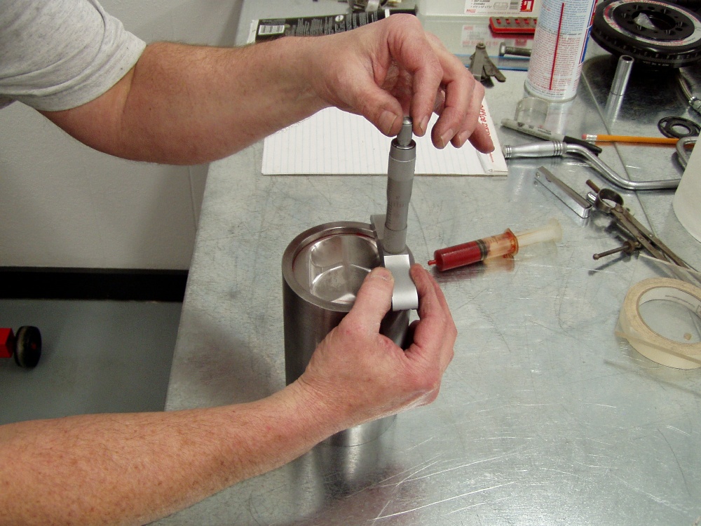
 We place one of the pistons in a steel sleeve of the exact cylinder bore
diameter. The depth is just enough to clear the dome's highest point. We measure
and record the distance from the top of the cylinder to the intake quench pad of
the piston. Red grease is used to make a fluid-tight seal between the piston and
the sleeve. We place one of the pistons in a steel sleeve of the exact cylinder bore
diameter. The depth is just enough to clear the dome's highest point. We measure
and record the distance from the top of the cylinder to the intake quench pad of
the piston. Red grease is used to make a fluid-tight seal between the piston and
the sleeve.
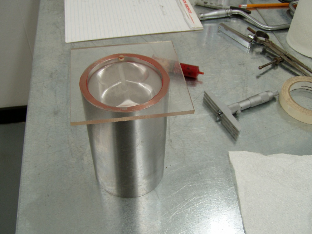
 A plexiglass plate is then placed atop the cylinder and the area above the
piston is filled with liquid to determine the piston's dome displacement. A plexiglass plate is then placed atop the cylinder and the area above the
piston is filled with liquid to determine the piston's dome displacement.
 After calculating the engine's compression ratio, it was determined that we
needed to remove some more material from the head's deck surface to obtain the
volume necessary. After calculating the engine's compression ratio, it was determined that we
needed to remove some more material from the head's deck surface to obtain the
volume necessary.
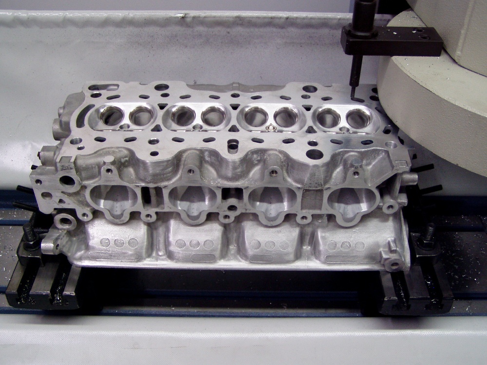
 Our Peterson milling machine is dedicated to precisely milling heads. It's
capable of machine as little as half a scribe line from the head's deck. We also
use this machine for squaring the head's deck to the cam bores early on in the
head's rework. Our Peterson milling machine is dedicated to precisely milling heads. It's
capable of machine as little as half a scribe line from the head's deck. We also
use this machine for squaring the head's deck to the cam bores early on in the
head's rework.
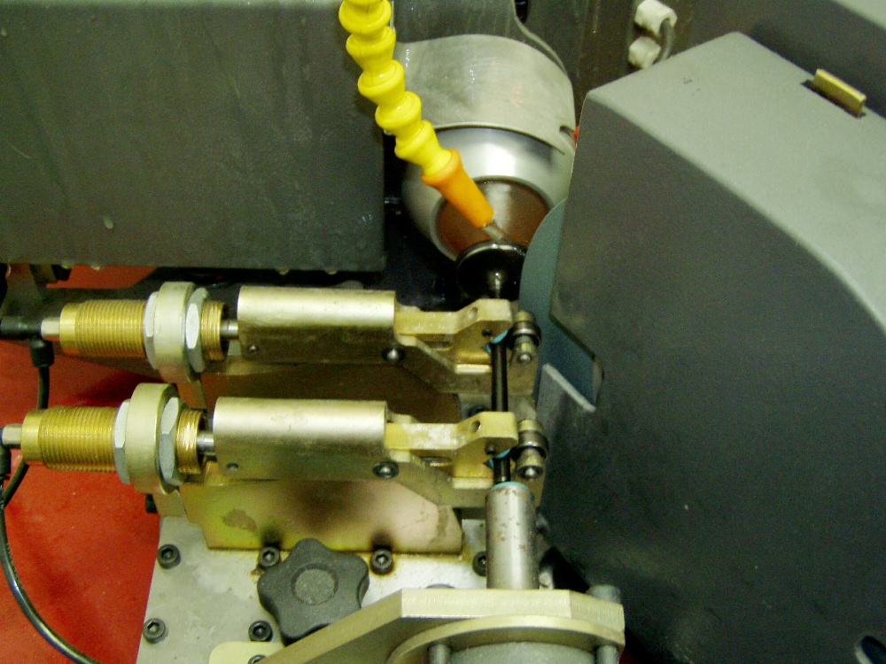
 We grind all the valves with the most accurate centerless valve facing
machine available to achieve face run-out measurements of less than .0001". We grind all the valves with the most accurate centerless valve facing
machine available to achieve face run-out measurements of less than .0001".
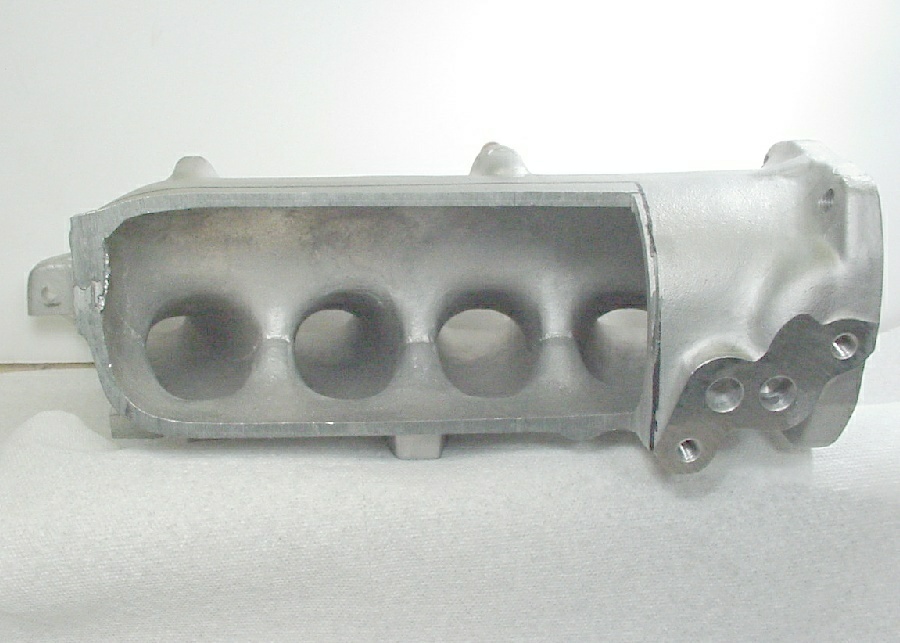
 Our manifold preparation for one of these engines begins with a Skunk2
casting. We cut the plenum in half to facilitate the porting and plenum
reshaping. Our manifold preparation for one of these engines begins with a Skunk2
casting. We cut the plenum in half to facilitate the porting and plenum
reshaping.
 When I tell people that these manifolds weigh as much as 2 lbs less when
we're finished, they think I'm kidding. Believe it. We rather dramatically alter
the runner volumes, cross sectional areas, window shapes, and plenum entry
geometries in this rework. When I tell people that these manifolds weigh as much as 2 lbs less when
we're finished, they think I'm kidding. Believe it. We rather dramatically alter
the runner volumes, cross sectional areas, window shapes, and plenum entry
geometries in this rework.
 Here's the semi-finished manifold interior. The runner roofs are now shorter
than the floor, by exactly the ports' dimensional differences. Note the inverted
radius we achieve at the upper runner-to-plenum intersect. With the plenum side
in place and a 64mm throttle body, this manifold will out-flow the best
individual throttle body combination we've ever tested. At .500" valve lift
the head/manifold combination will flow 349cfm @ 28"H20 with equally
impressive mid-lift numbers. Here's the semi-finished manifold interior. The runner roofs are now shorter
than the floor, by exactly the ports' dimensional differences. Note the inverted
radius we achieve at the upper runner-to-plenum intersect. With the plenum side
in place and a 64mm throttle body, this manifold will out-flow the best
individual throttle body combination we've ever tested. At .500" valve lift
the head/manifold combination will flow 349cfm @ 28"H20 with equally
impressive mid-lift numbers.
 We have to use retainers that set-up .060" higher than stock. This can
lead to retainer-to-rocker arm contact. It's essential that the clearance
between the retainer and the rocker arm be at least .040". We check this
clearance on every head we rework and assemble, as failure to do so can result
in catastrophic engine damage We have to use retainers that set-up .060" higher than stock. This can
lead to retainer-to-rocker arm contact. It's essential that the clearance
between the retainer and the rocker arm be at least .040". We check this
clearance on every head we rework and assemble, as failure to do so can result
in catastrophic engine damage
 .
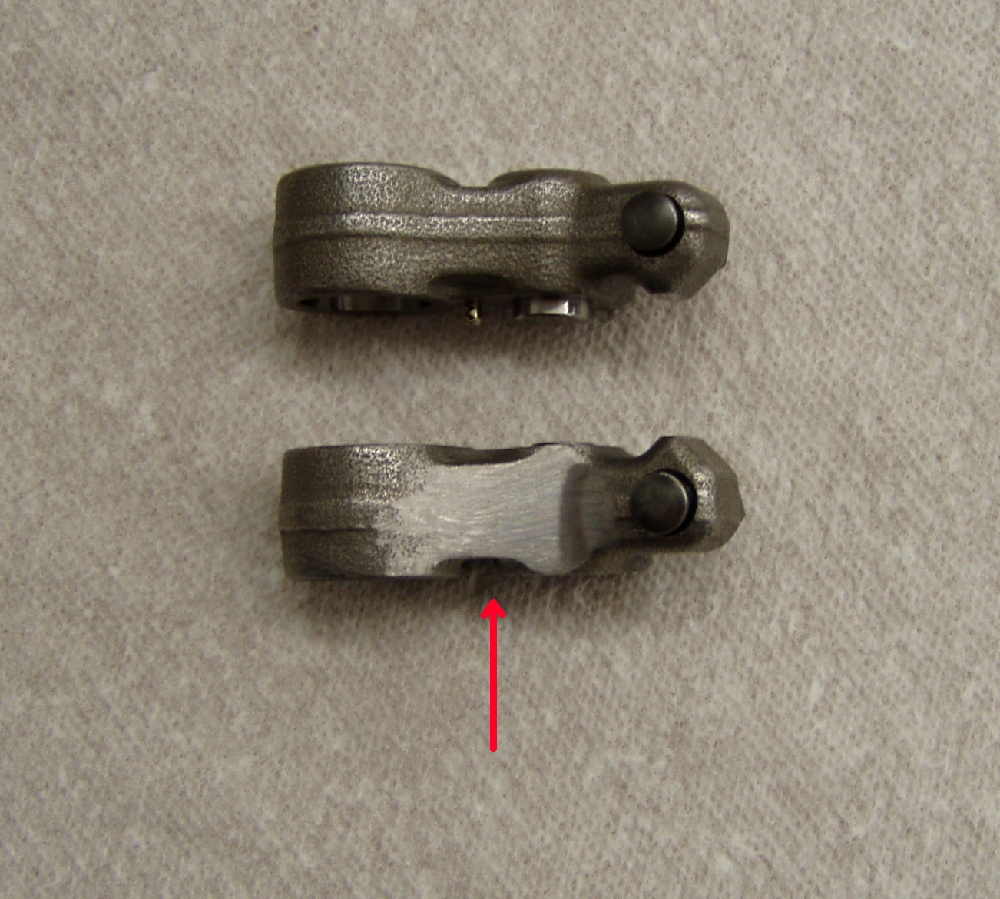
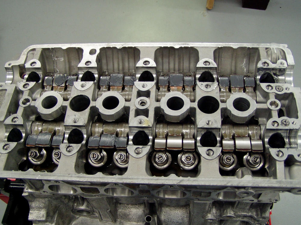
In this photo, you can see the material removal necessary to achieve
retainer-to-rocker arm clearance. Any grinding marks must travel
length-wise on the rocker to eliminate possible stress-risers. .
In this photo, you can see the material removal necessary to achieve
retainer-to-rocker arm clearance. Any grinding marks must travel
length-wise on the rocker to eliminate possible stress-risers.
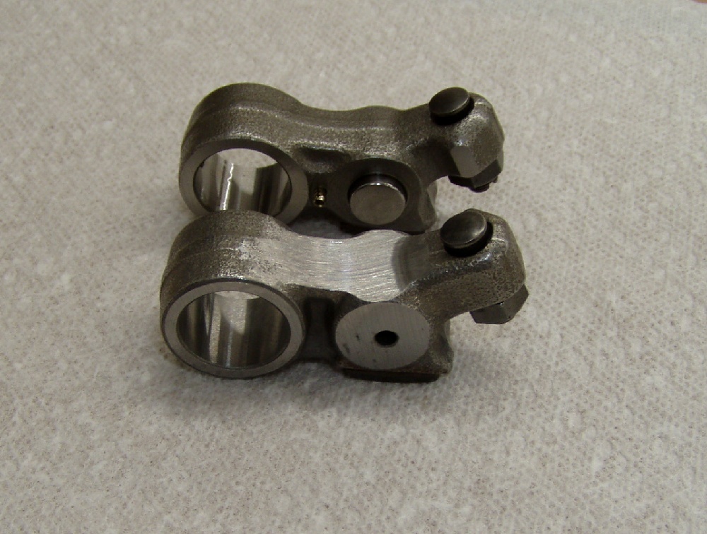
 Another view of the modified rocker arm. Another view of the modified rocker arm.
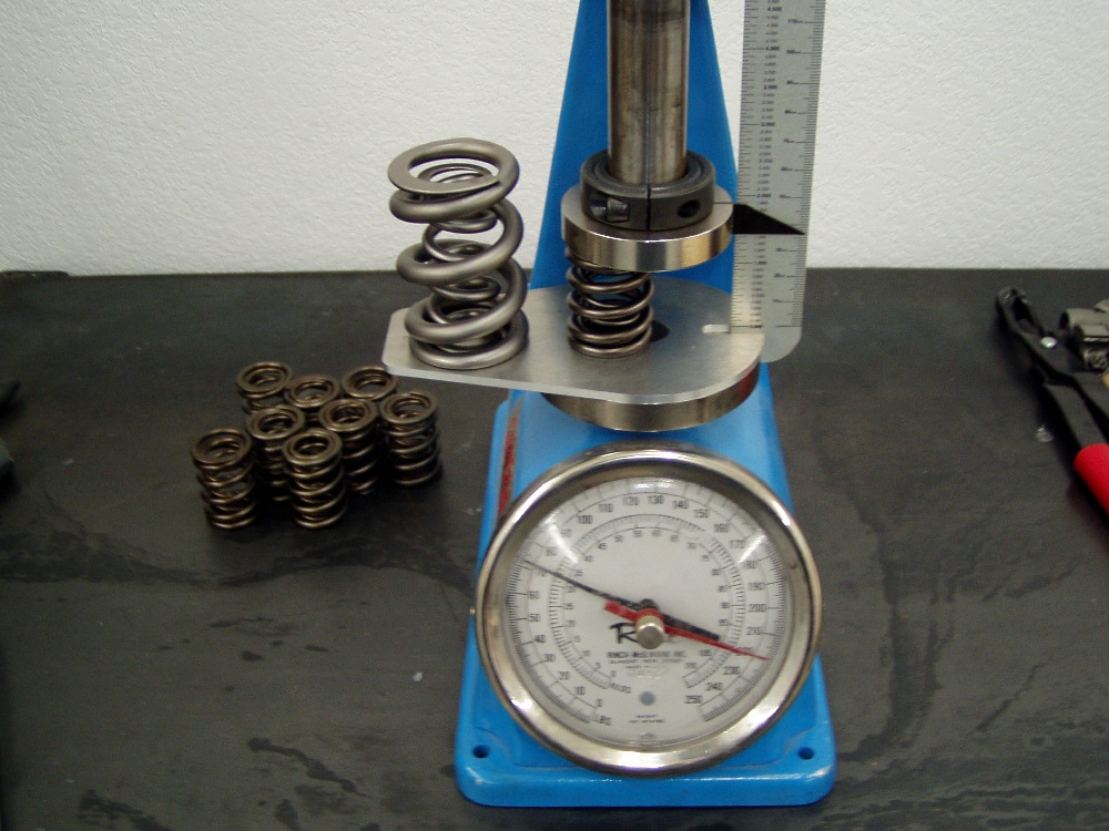
 Here's a reality check for you. At the left is our newest spring for the B
series engines. It's stable to 12,000 rpm. It specs out at 70psi on the seat
with 222 nose pressure at .550" lift. Price is $400.00 per set. At the
right is a Pro Stock spring that's used by all the top running teams. It's made
of titanium. it costs $400.00 (per spring) and it's capable of controlling valve
motion at 12,000 rpm. It's a throw away item after 8 runs. Pressure......you
could put one of these atop your car's shock absorbers and chunk the springs. If
import racing survives, you'll be seeing this sort of thing in the future, as
racing becomes more lucrative and competitive. Here's a reality check for you. At the left is our newest spring for the B
series engines. It's stable to 12,000 rpm. It specs out at 70psi on the seat
with 222 nose pressure at .550" lift. Price is $400.00 per set. At the
right is a Pro Stock spring that's used by all the top running teams. It's made
of titanium. it costs $400.00 (per spring) and it's capable of controlling valve
motion at 12,000 rpm. It's a throw away item after 8 runs. Pressure......you
could put one of these atop your car's shock absorbers and chunk the springs. If
import racing survives, you'll be seeing this sort of thing in the future, as
racing becomes more lucrative and competitive.
 We test each and every spring for installed pressure and open pressure. We test each and every spring for installed pressure and open pressure.
 In order to accommodate the springs' installed heights, we machined
.025" off the bottom of the stock Honda spring seats. In order to accommodate the springs' installed heights, we machined
.025" off the bottom of the stock Honda spring seats.
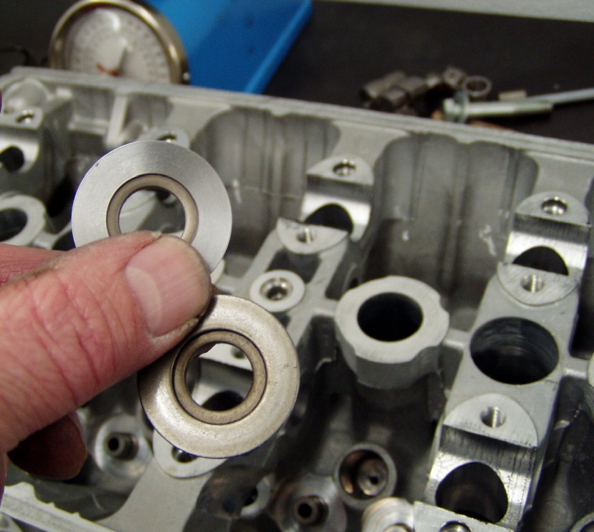
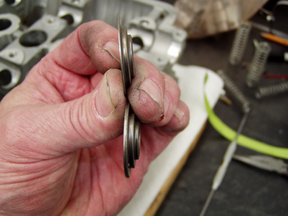
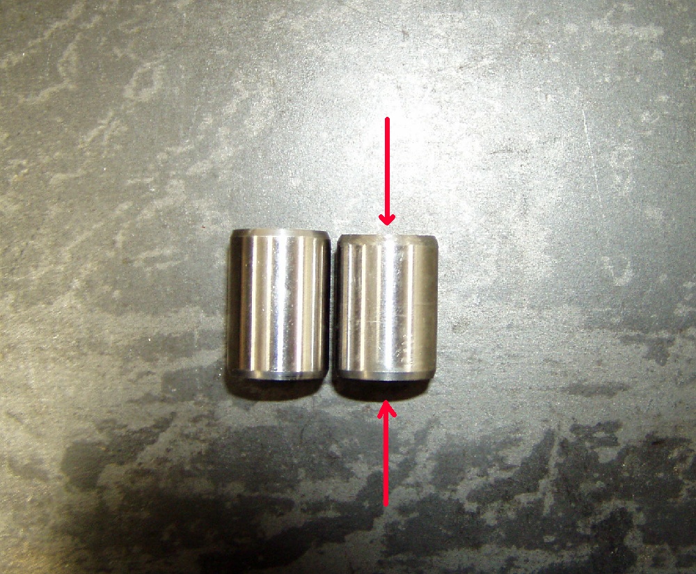
 This view shows the difference between our modified spring seat and the
stocker's thickness. We coat the underside of these seats for increased
lubricity prior to installation. This view shows the difference between our modified spring seat and the
stocker's thickness. We coat the underside of these seats for increased
lubricity prior to installation.
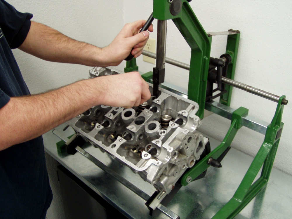
 Assembling these heads with the springs positioned "deep" in the
head requires a lot of patience, or a fixture like this designed for the task. Assembling these heads with the springs positioned "deep" in the
head requires a lot of patience, or a fixture like this designed for the task.
 We use ITR lost motion devices in any head running cams with more than
.425" valve lift. Note the high pressure lube on the top of the valve
stems. We use ITR lost motion devices in any head running cams with more than
.425" valve lift. Note the high pressure lube on the top of the valve
stems.
 We machine the dowel holes in the heads deeper than Honda does, but for those
of you milling blocks, heads, and or using thinner-than-stock head gaskets, it's
essential to shorten the locating dowels by at least the amount of material
removed to prevent the head from sitting "up" at the corners. Failure
to do so can result in oil-leaking head gaskets. We machine the dowel holes in the heads deeper than Honda does, but for those
of you milling blocks, heads, and or using thinner-than-stock head gaskets, it's
essential to shorten the locating dowels by at least the amount of material
removed to prevent the head from sitting "up" at the corners. Failure
to do so can result in oil-leaking head gaskets.
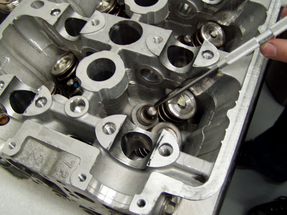
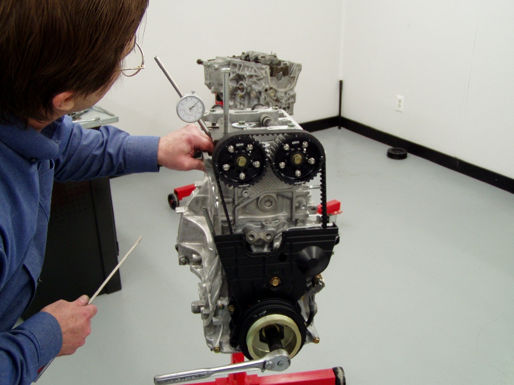
 It's also mandatory that you check piston to valve clearance with any
non-stock combination you assemble. If you "assume" it'll be OK
because you know of someone else running the combination, you're asking for
trouble. I use the same fixture we use on the flow bench to place the indicator
on the valve retainer. It's also mandatory that you check piston to valve clearance with any
non-stock combination you assemble. If you "assume" it'll be OK
because you know of someone else running the combination, you're asking for
trouble. I use the same fixture we use on the flow bench to place the indicator
on the valve retainer.
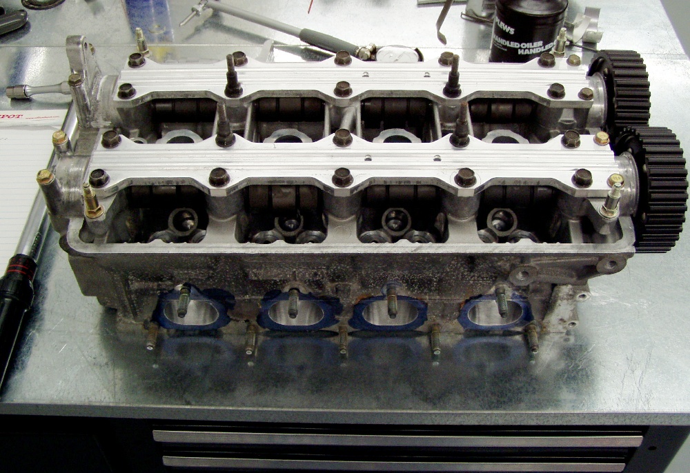
 If you look closely, you can see the heads of the exhaust valves behind the
intakes in this photo. This particular head/valve/cam combination has .030"
"clicking clearance". Sort of scary knowing that if one side is just a
touch too quick, or too slow, the valves will lock and the engine will be
history when the piston "closes" them. If you look closely, you can see the heads of the exhaust valves behind the
intakes in this photo. This particular head/valve/cam combination has .030"
"clicking clearance". Sort of scary knowing that if one side is just a
touch too quick, or too slow, the valves will lock and the engine will be
history when the piston "closes" them.
 We use moly-lube on the rocker arms, to insure that there will be as little
friction as possible with the cam's new lobes. Keep observers will note that
these rockers have been treated to new altered-radius wiper pads, which are furnace
brazed to the rocker bodies and ground to work properly with the cams' lobes. We use moly-lube on the rocker arms, to insure that there will be as little
friction as possible with the cam's new lobes. Keep observers will note that
these rockers have been treated to new altered-radius wiper pads, which are furnace
brazed to the rocker bodies and ground to work properly with the cams' lobes.
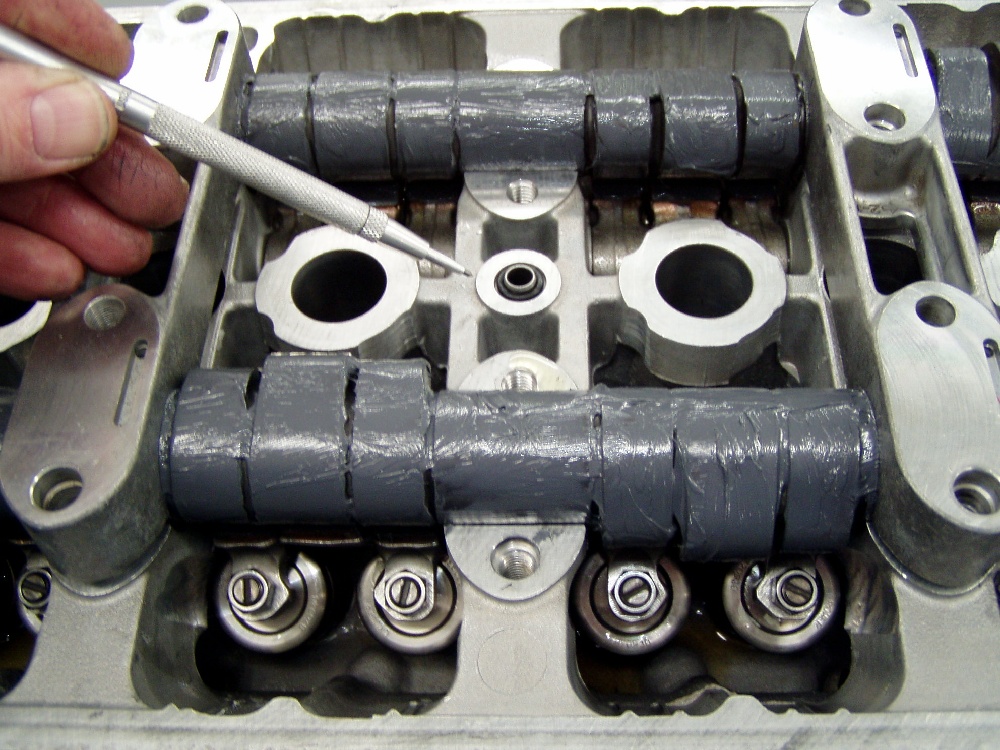
 Before the final installation of the cam caps, make sure to put the oil dowel
and "O" ring in the head under the center cap. Yes, we lube the hell
out of the camshafts. Before the final installation of the cam caps, make sure to put the oil dowel
and "O" ring in the head under the center cap. Yes, we lube the hell
out of the camshafts.
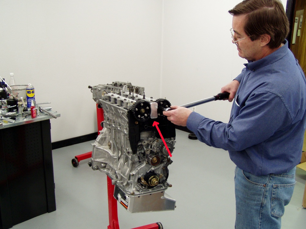
 Torque the cam bolts to factory specs. Do not use an impact to tighten
the bolts... Note our fixture that inserts pins between the cam gears, locking
them together at a "straight-up" position for torquing and installing
the timing belt. Torque the cam bolts to factory specs. Do not use an impact to tighten
the bolts... Note our fixture that inserts pins between the cam gears, locking
them together at a "straight-up" position for torquing and installing
the timing belt.
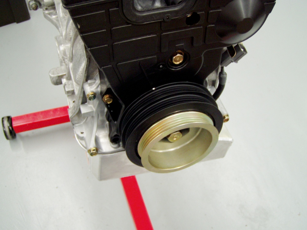
 Prior to installation, I always mark the harmonic balancer 180 degrees
opposite the TDC mark to facilitate setting the valves. Note that this is a
stock (neutral-balanced) ITR balancer we're using. Always use a new crank bolt
for the installation. Prior to installation, I always mark the harmonic balancer 180 degrees
opposite the TDC mark to facilitate setting the valves. Note that this is a
stock (neutral-balanced) ITR balancer we're using. Always use a new crank bolt
for the installation.
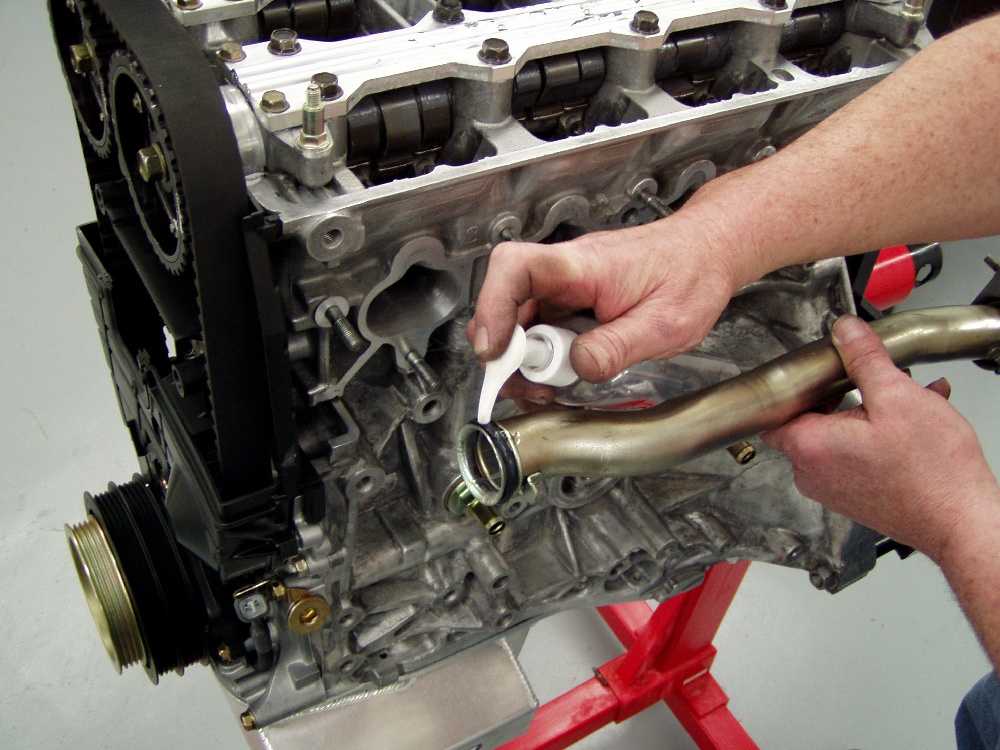
 I always use liquid hand soap for installing "O" rings and hoses
with minimal "fuss". I always use liquid hand soap for installing "O" rings and hoses
with minimal "fuss".
 We're using two breather tanks on this high-revving engine. The block
fittings are the same ones we sell, with the anti-siphon tubes for increased
efficiency in separating oil. Note the sealant that's standard issue on the
threads. We're using two breather tanks on this high-revving engine. The block
fittings are the same ones we sell, with the anti-siphon tubes for increased
efficiency in separating oil. Note the sealant that's standard issue on the
threads.
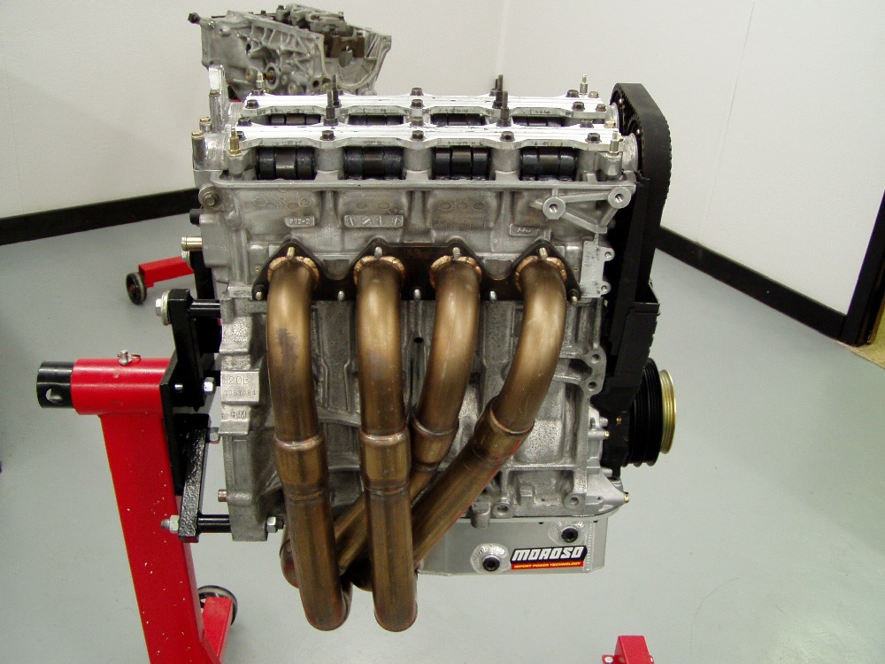
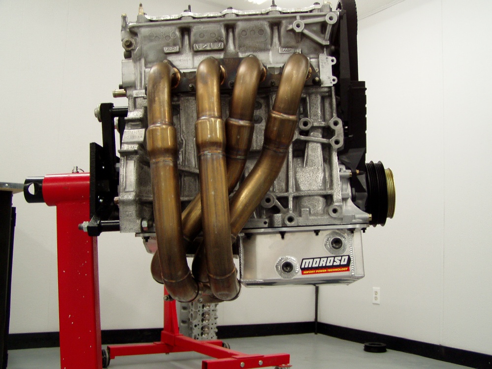
 Checking for fitment on our "killer" header from John at Hytech.
Note that he configured it for AC clearance. This header is the veteran of many
dyno pulls on similar 2-liter engines we've built, so it's a known quantity. Checking for fitment on our "killer" header from John at Hytech.
Note that he configured it for AC clearance. This header is the veteran of many
dyno pulls on similar 2-liter engines we've built, so it's a known quantity.
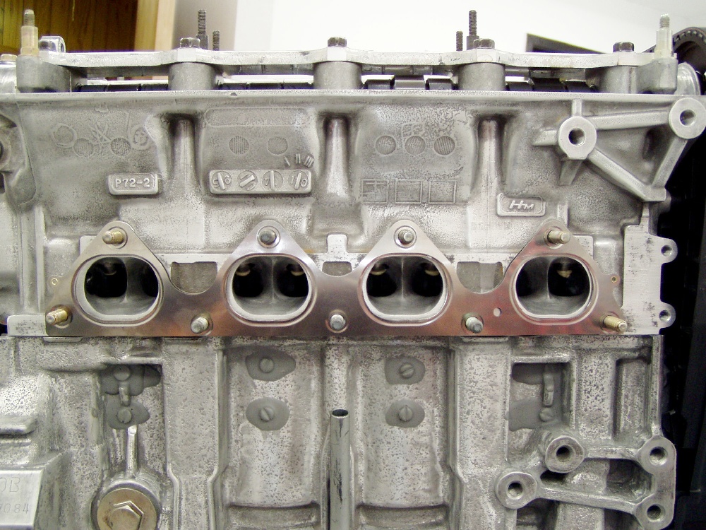
 Don't be mislead by the picture, but it's imperative that the header (and
intake) gaskets do not hang in the way of the flow. If you don't trim the
gaskets, you're potentially sacrificing any possible gains from porting. We trim
the gaskets to be approximately .050" larger all the way around the port.
This gasket is situated ahead of the flange on the studs, producing the illusion
that the openings are much larger than the ports. Don't be mislead by the picture, but it's imperative that the header (and
intake) gaskets do not hang in the way of the flow. If you don't trim the
gaskets, you're potentially sacrificing any possible gains from porting. We trim
the gaskets to be approximately .050" larger all the way around the port.
This gasket is situated ahead of the flange on the studs, producing the illusion
that the openings are much larger than the ports.
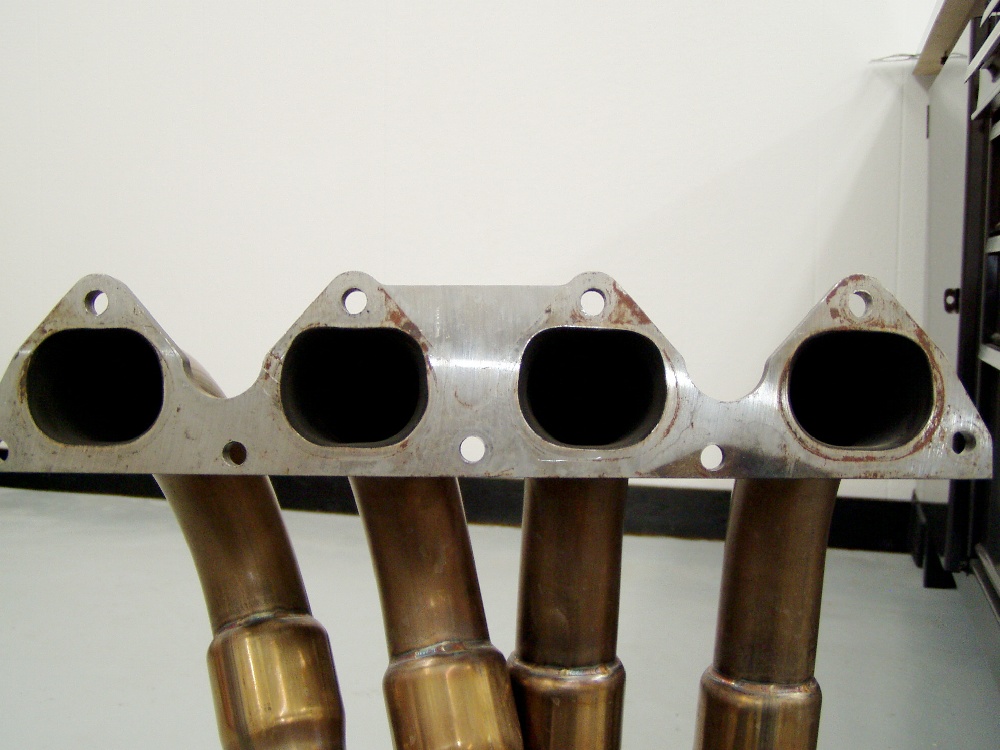
 Note that the header primary pipes are configured to work with our raised
port roofs. Note that the header primary pipes are configured to work with our raised
port roofs.
 Oil heater? We'll make sure there's some separation here before installation.
I'm also raising secondary pipes and collector about 1.5" for better
in-vehicle ground clearance, which is important on the streets of Ft. Worth. Oil heater? We'll make sure there's some separation here before installation.
I'm also raising secondary pipes and collector about 1.5" for better
in-vehicle ground clearance, which is important on the streets of Ft. Worth.
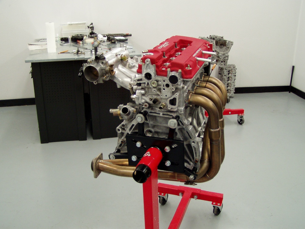
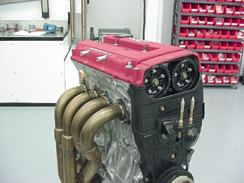
 It's almost ready for installation at this point. It's almost ready for installation at this point.
 Note that we've shortened the vent tubes in the valve cover and cut the valve
cover and plastic shroud to facilitate cam timing changes. Note that we've shortened the vent tubes in the valve cover and cut the valve
cover and plastic shroud to facilitate cam timing changes.
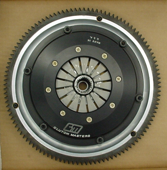
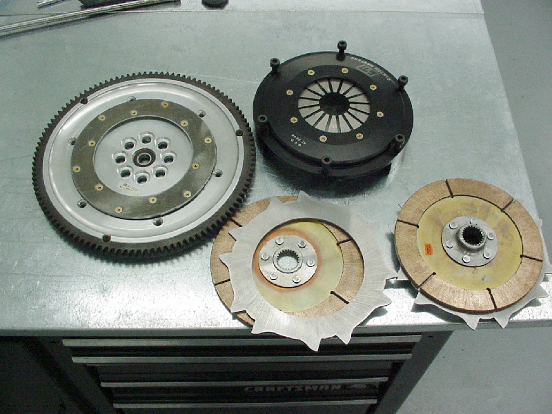
 In the box, here's our custom CM clutch and flywheel combination. In the box, here's our custom CM clutch and flywheel combination.
 Lots of pieces fit into small spaces with this package. Note the sculpting to
reduce flywheel mass and the small diameter of the pressure plate, disks and
floaters. This set-up is extremely lightweight and capable of handling a lot of
abuse, including shifts over 10K. Lots of pieces fit into small spaces with this package. Note the sculpting to
reduce flywheel mass and the small diameter of the pressure plate, disks and
floaters. This set-up is extremely lightweight and capable of handling a lot of
abuse, including shifts over 10K.
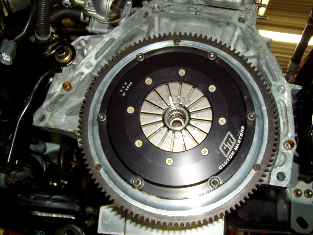
 Here's the CM twin-disk bolted to the crank. Here's the CM twin-disk bolted to the crank.
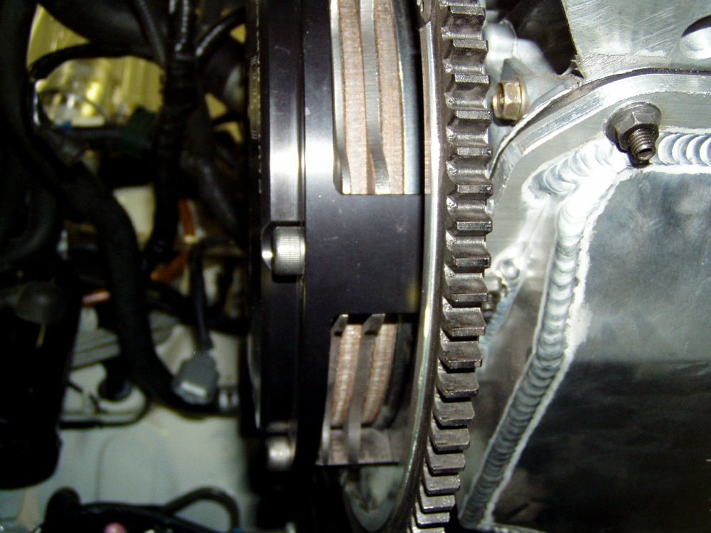
 Nice stack of components fit into a mall space. Nice stack of components fit into a mall space.
 I believe in maximizing the rigidity of the block / transmission assembly. We
had to reconfigure Honda's brace to fit properly with the Moroso oil pan.
Details like this are important to building a long-lasting combination. I believe in maximizing the rigidity of the block / transmission assembly. We
had to reconfigure Honda's brace to fit properly with the Moroso oil pan.
Details like this are important to building a long-lasting combination.
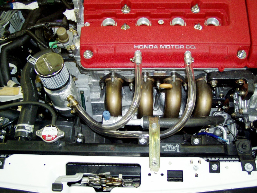
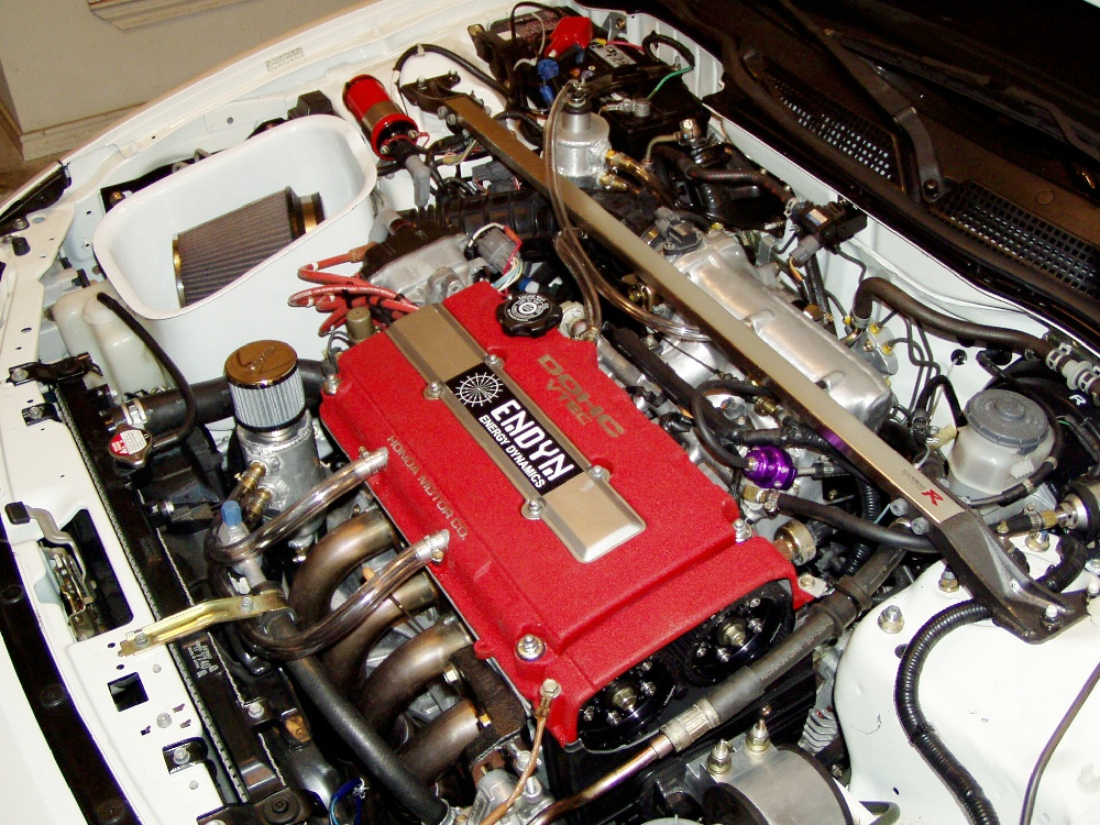
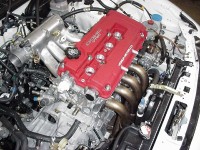 Engine's installed in the car with a few details remaining before it's
running. Engine's installed in the car with a few details remaining before it's
running.
 This view shows the rear breather tank plumbing, as well as the nifty GEM
accessory oil outlet and the nylon tubing leading to the in-car oil pressure
gauge. This view shows the rear breather tank plumbing, as well as the nifty GEM
accessory oil outlet and the nylon tubing leading to the in-car oil pressure
gauge.
 2-liter engines produce tremendous crankcase pressures at high rpm levels, so
we've plumbed this engine with our valve cover vent system to make life easier
on it. 2-liter engines produce tremendous crankcase pressures at high rpm levels, so
we've plumbed this engine with our valve cover vent system to make life easier
on it.
 It's on the road again. Note that we haven't had time to construct a worthy
induction tube, but the stock ITR tube just happened to reach the intake plenum
and delivers plenty of filtered air to the engine for break-in driving. It's on the road again. Note that we haven't had time to construct a worthy
induction tube, but the stock ITR tube just happened to reach the intake plenum
and delivers plenty of filtered air to the engine for break-in driving.
 Another view of the engine in it's current break-in condition. We'll be
updating the article as time (and miles) pass. Another view of the engine in it's current break-in condition. We'll be
updating the article as time (and miles) pass.
|